iClient S100
Context
Before configuring basic device information on the iClient S100, you need to configure basic information on the OMU portal by referring to Configuring Basic Information or configure the startup wizard on the LDU by referring to Configuring the Startup Wizard. For details about how to configure user information before connecting devices to the iClient S100, see (Optional) Configuring User Information.
Connecting to the iClient S100
Operating Environmental Requirements
Category |
Minimum Configuration |
Recommended Configuration |
|---|---|---|
CPU |
Intel i5-2200 |
Intel Core i7-8700 or later |
Available memory |
4 GB |
At least 16 GB (DDR4 1600 MHz or higher) |
Hard disk |
500 GB (adjusted based on the size of the local recording and snapshot storage space) and 15 GB available system disk space |
At least 500 GB (adjusted based on the size of the local recording and snapshot storage space) and at least 15 GB available system disk space |
Operating system |
64-bit Windows 7 Professional and 64-bit Windows 10 |
64-bit Windows 10 |
Graphics card |
Intel integrated graphics card with a video RAM of 2.0 GB (Intel® HD Graphics 530 or higher is recommended.) |
Intel integrated graphics card with a video RAM of more than 2.0 GB (Intel® HD Graphics 620 or higher is recommended.) |
Network adapter |
One 1000 Mbit/s network adapter |
One 1000 Mbit/s network adapter |
Monitor |
To ensure the display effect, you are advised to use a monitor of at least 22 inches, and set the resolution to 1920 x 1080 pixels and aspect ratio to 100%. |
To ensure the display effect, you are advised to use a monitor of at least 22 inches, and set the resolution to 1920 x 1080 pixels and aspect ratio to 100%. |
System time and time zone |
The time and time zone of the computer where the client resides and the computer where the server resides must be the same as those of the main device (HWT-IVS1800). You can set the system time and time zone on the computer under Start > Control Panel > Clock, Language, and Region. |
|

- The system cannot run in any of the following environments:
- Operating systems running as VMs
- Operating systems except Windows 7 and Windows 10
- Computer memory being less than 4 GB
- System disks whose available space is less than 2 GB
- Operating systems except Microsoft official ones
- The system cannot be installed in the following environments (not supported if any of the following conditions is met):
- Operating systems whose users are not administrators
- 32-bit operating system
- All export and import functions can be used only in the following environments:
- The Office Excel has been installed with a license activated and runs properly.
- Configuration A: i5-6600 CPU @3.10 GHz; memory: 8 GB; 64-bit Windows 7 Professional; integrated graphics card: Intel® HD Graphics 530.
- Configuration B: i7-6700 CPU @3.2 GHz; memory: 16 GB; 64-bit Windows 10 Professional (subversion: 17763); integrated graphics card: Intel® HD Graphics 530.
- Configuration C: i7-8700 CPU @3.2 GHz; memory: 16 GB; 64-bit Windows 10 Professional (subversion: 17763); integrated graphics card: Intel® UHD Graphics 630.
Table 3-45 Number of live video channels supported by the iClient S100
Resolution
Configuration A (H.264)
Configuration A (H.265)
Configuration B (H.264)
Configuration B (H.265)
Configuration C (H.264)
Configuration C (H.265)
CIF (512 kbit/s)
38
38
60
42
64
60
4CIF/D1 (1 Mbit/s)
22
22
45
36
50
45
720p (2 Mbit/s@25 fps)
10
10
16
14
34
30
1080p (4 Mbit/s@25 fps)
6
6
14
10
20
14
3840 x 2160 (12 Mbit/s@25 fps)
1
1
3
1
4
4
(Optional) Configuring User Information
Context
On the OMU portal, you can configure the Administrator, Operator, Administrator (ISV), Operator (ISV), Live video operator (man-machine), Recording operator (man-machine), and Recording administrator (man-machine) roles.
- The admin user is a predefined user with full permissions on the system. The role and name of the admin user are specified by default and unconfigurable.
- The Administrator and Administrator (ISV) roles have the same permissions.
- The Administrator role is used to log in to the iClient S100 or OMU portal.
- The Administrator (ISV) role is used to connect the third-party VIID or comprehensive video platform to the HWT-IVS1800.
- The Operator and Operator (ISV) roles have the same permissions.
- The Operator role is used to log in to the OMU portal.
- The Operator (ISV) role is used to connect the third-party VIID or comprehensive video platform to the HWT-IVS1800.
The following describes the permissions of users with different roles on the OMU portal, iClient S100, and .
OMU portal
Table 3-46 describes the OMU portal permissions of users with different roles.
Function Permission |
admin |
Administrator |
Operator |
Administrator (ISV) |
Operator (ISV) |
Live Video Operator (Man-Machine) |
Recording Operator (Man-Machine) |
Recording Administrator (Man-Machine) |
|---|---|---|---|---|---|---|---|---|
Login/Logout |
Yes |
Yes |
Yes |
Yes |
Yes |
Yes |
Yes |
Yes |
Password change |
Yes |
Yes |
Yes |
Yes |
Yes |
Yes |
Yes |
√ |
Restart |
Yes |
No |
No |
No |
No |
No |
No |
No |
Home page |
Yes |
Yes |
Yes |
Yes |
Yes |
No |
No |
No |
System management |
Yes |
Yes (Network and time settings can be viewed only.) |
Yes (Only basic configurations are supported.) |
Yes (Network and time settings can be viewed only.) |
Yes (Only basic configurations are supported.) |
No |
No |
No |
Connection management |
Yes |
Yes (Not supported for certificate management and cloud service connection.) |
No |
Yes (Not supported for certificate management and cloud service connection.) |
No |
No |
No |
No |
Maintenance and management |
Yes |
Yes (Not supported for the Data Safe management and log management.) |
No |
Yes (Not supported for the Data Safe management and log management.) |
No |
No |
No |
No |
Storage management |
Yes |
Yes |
No |
Yes |
No |
No |
No |
No |
Inspection |
Yes |
Yes |
No |
Yes |
No |
No |
No |
No |
Fault information collection |
Yes |
No |
No |
No |
No |
No |
No |
No |
Upgrade |
Yes |
Yes (The upgrade can be performed by invoking the interface through port 8443 on the iClient S100.) |
No |
Yes (The upgrade can be performed by invoking the interface through port 8443 on the iClient S100.) |
No |
No |
No |
No |
User management |
Yes |
No |
No |
No |
No |
No |
No |
No |
Intelligent service authorization |
Yes |
No |
No |
No |
No |
No |
No |
No |
Modification of Security Questions and Their Answers |
Yes |
No |
No |
No |
No |
No |
No |
No |
iClient S100
Table 3-47 describes permissions of users with varied roles on the iClient S100. Only the administrator can log in to the iClient S100.
Function Permission |
admin |
Administrator |
Operator |
Administrator (ISV) |
Operator (ISV) |
|---|---|---|---|---|---|
Video device |
Yes |
Yes |
No |
Yes |
No |
Recording management |
Yes |
Yes |
No |
Yes |
No |
Alarm management |
Yes |
Yes |
No |
Yes |
No |
Recording bookmark management |
Yes |
Yes |
No |
Yes |
No |
Log management |
Yes |
Yes |
No |
Yes |
No |
Alarm handling |
Yes |
Yes |
No |
Yes |
No |
Snapshot management |
Yes |
Yes |
No |
Yes |
No |
Live video viewing |
Yes |
Yes |
No |
Yes |
No |
Recording playback |
Yes |
Yes |
No |
Yes |
No |
Recording download |
Yes |
Yes |
No |
Yes |
No |
Voice |
Yes |
Yes |
No |
Yes |
No |
Basic PTZ controls |
Yes |
Yes |
No |
Yes |
No |
Manual recording |
Yes |
Yes |
No |
Yes |
No |
Snapshot taking |
Yes |
Yes |
No |
Yes |
No |
Advanced PTZ controls |
Yes |
Yes |
No |
Yes |
No |
System configuration management |
Yes |
Yes |
No |
Yes |
No |
Intelligent analysis task viewing |
Yes |
Yes |
No |
Yes |
No |
Intelligent analysis task search |
Yes |
Yes |
No |
Yes |
No |
Static list viewing |
Yes |
Yes |
No |
Yes |
No |
Static list management |
Yes |
Yes |
No |
Yes |
No |
Trustlist management |
Yes |
Yes |
No |
Yes |
No |
Upgrade |
Yes |
Yes |
No |
Yes |
No |
Intelligent alert task |
Yes |
Yes |
No |
Yes |
No |
Intelligent analysis alert |
Yes |
Yes |
No |
Yes |
No |
Intelligent analysis task management |
Yes |
Yes |
No |
Yes |
No |
Procedure
Select a role to create a user based on the site requirements. User roles are configured in similar procedures. This section uses Administrator as an example.
- Log in to the OMU portal as the admin user and configure the Administrator role.
- Log in to the OMU portal as the admin user. (
 Logging In to the OMU portal)
 - Choose Users > Manage User.
- Click Add User.
- Configure an administrator, as shown in Figure 3-72.
Table 3-48 describes the parameters.
Table 3-48 Parameter descriptionParameter
Description
Role
User role. Select Administrator.
User Name
User name and password. You are advised to create a complex password. For details about password complexity requirements, see Suggestions on Password Maintenance.
Password
Confirm Password
Multi-point Logins
Maximum number of computers where a user can add HWT-IVS1800 on the iClient S100 and log in to the OMU portal at the same time.
For example, if this parameter is set to N, a user can add through the iClient on N computers and log in to the OMU portal on N computers at the same time.
PTZ Control Priority
PTZ control priority. The value ranges from 1 to 32 in descending order of priority.
Validity Period
- If you toggle on Validity Period, the user account is valid only within the specified period.
- If you toggle off Validity Period, the user account is permanently valid.
For security purposes, you are advised to select this check box.
Effective Time/Expiration Time
Device Viewing Permissions
Indicates whether to allow a user to view all cameras connected to the HWT-IVS1800, including existing connected cameras and cameras to be connected later. This function is disabled by default.
Description
User description.
- (Optional) If you do not set Device Viewing Permissions to All or Partial Activation in 1.d, perform the following steps to assign camera viewing permissions to the new user:
- Click Permissions next to the new account in the UserList area.
- Assign camera viewing permissions to the new account, as shown in Figure 3-73.
If you click All, the new user can view all cameras connected to the , including existing connected cameras and cameras to be connected later. If you click Partial Activation, you need to manually select devices in the device list to assign camera viewing permissions to the user.
- (Optional) If there are multiple HWT-IVS1800s, perform steps 1.a through 1.e to add users for each of them.
- Log in to the OMU portal as the admin user. (
- Log in to the OMU portal as the new user.
- Click Log Out to log out the admin user.
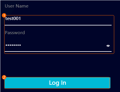
- Log in to the OMU portal as the new user, as shown in Figure 3-74.
Table 3-49 describes the parameters.
Table 3-49 Parameter descriptionParameter
Description
User Name
The user name and password must be the same as those set in Figure 3-72.
Password
- Click OK when the message "The first time you log in, please change your password" is displayed.
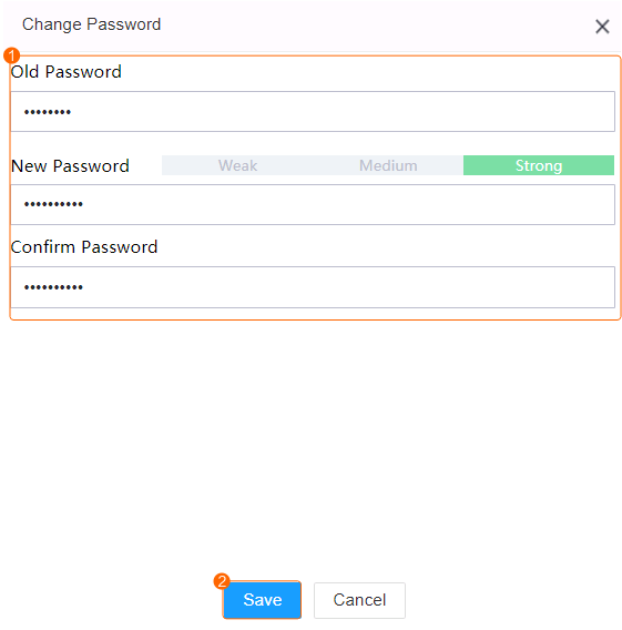
- Change the password, as shown in Figure 3-75.
Table 3-50 describes the parameters.
Table 3-50 Parameter descriptionParameter
Description
Old Password
Old password, which must be the same as that set in Figure 3-72.
New Password
New password. You can customize a password and a password with high complexity is required. For details about password complexity requirements, see Suggestions on Password Maintenance.
Confirm Password
- Use the new password to log in to the OMU portal again.


Downloading and Installing the iClient S100

- To ensure that new functions can be properly used on each client in the iClient S100 system, you need to upgrade software of servers and all clients in the system at the same time.
- For the iClient S100 of V1.3.0 and later versions, the client version must be the same as the server version. Otherwise, the client cannot access the server.
- The plug-in functions are available only in the iClient S100 of V3.3.0 and earlier versions.
- To use functions such as attendance, access control, electronic map, and personnel management on the iClient S100 of a version later than V3.0.0, you need to install the required plug-in package first.
- After the iClient S100 is installed, you can right-click the DLL file and choose Properties from the shortcut menu to view the certificate expiration date (October 1, 2026). The iClient S100 can still be used after this date.
- Right-click the client installation program and choose Run as administrator from the shortcut menu. Select a language and click OK.
- (Optional) Click Overwrite installation or Uninstall and reinstall when the system detects that the iClient S100 client has been installed on the computer, as shown in Figure 3-76. (This step is not required for the first installation.)
- If you click Overwrite installation, go to 3 for subsequent operations.
- If you click Uninstall and reinstall, you need to uninstall the original client as prompted. After the uninstallation is complete, the system automatically goes to the next step.
You are advised to choose Overwrite installation, in which case devices (including their configurations) added and basic configurations set on the original iClient S100 will be retained.
- Select an installation mode (for example, Server+Client), and click Next.
- Installation modes include the Server+Client mode and the Client mode. You can select a mode based on the site requirements.
- Select the installation directory and click Next. In the window that is displayed, click Next.
- The default installation path is C:\Program Files\iClient S100-B. You can also click Browse to specify an installation path. Ensure that the selected installation path has sufficient disk space as prompted.
- After you click Next during overwrite installation, the port number and installation path of the server remain unchanged and require no configuration.
- Click Install to install the software.
- After the software is installed, you need to wait for about 2 minutes until all services start before performing operations.
- If the computer running the server has two network adapters, you need to set the service IP address on the server based on the site requirements. For details, see the iClient S100 product documentation.

Connecting an HWT-IVS1800
Prerequisites
The network between the computer running the iClient S100 and the device is normal.
Procedure
- Start the iClient S100.
- In Windows 7, double-click the iClient S100 icon. The iClient S100 login page is displayed.
- In Windows 10, right-click the iClient S100 icon, choose Properties from the shortcut menu, click the Compatibility tab, select Run as an administrator, and click OK. Then double-click the iClient S100 icon on the desktop. The iClient S100 login page is displayed.
- Log in to the iClient S100. Figure 3-77 shows the login page.
Table 3-51 Parameter/Button description
Parameter/Button
Description
Chinese/English
Language used in the iClient S100.
User Name/Password
User name and password of the administrator or new user for logging in to the iClient S100.
For details about how to create a user, see in the iClient S100 User Manual.NOTE:- You need to set the password upon the first login.
- You can click
 to clear the password. You can also hold the mouse button down on
  to display the current password.
Remember password
Indicates whether to save the password corresponding to the user name (automatically saved by default) used for the last login.
Forgot password
Button for password retrieval. If you have bound your account to an email address, you can retrieve your password using the email address.
For details about how to bind your account to an email address, see in the iClient S100 User Manual.
For details about how to set email-related parameters, see in the iClient S100 User Manual.
Authentication
Basic: Use the default user admin or a new user to log in. This is the most common login method.
Port
Port number set when the server is installed. The default value is 58099.
If NAT has been configured, the port number is a post-NAT port number.
S100 Server IP
- If the Server+Client mode is enabled during the installation:
- Enter the local IP address 127.0.0.1 to use the local server.
- Enter the IP address of the computer where other servers are located to log in to the servers.
- If the Client mode is enabled during the installation:
Enter the IP address of the computer where the server to be connected is located.
CAUTION:Ensure that the computer where the server is installed is powered on and the network is normal. Otherwise, you will fail to log in to the server through the client.
- (Optional) When you log in to the client for the first time, determine whether to agree to the Intelligent Vision Facial Recognition Service Agreement on the page that is displayed. If you click Agree, the intelligent target analysis function is enabled. If you click Disagree, the intelligent target analysis function will not be enabled, and the related plug-in will be disabled. If you want to enable this function in the future, go to 4.
- (Optional) Choose on the iClient S100 home page.
Set Target Intelligence Enabled (Modifying this parameter will close all plugins) to Yes. The Intelligent Vision Facial Recognition Service Agreement page pops up. Click Agree and then click Save.
- Choose on the iClient S100 home page.
- On the page that is displayed, click Add in the upper left corner and choose IP Access. The page for adding a device is displayed, as shown in Figure 3-78. Table 3-52 describes the parameters.
Table 3-52 Parameters for adding a device
Parameter
Description
Device Type
Type of the device to be added. Set this parameter to IVS1800.
Address
IP address of the device to be added. The IP address is in xxx.xxx.xxx.xxx format, for example, 192.168.1.10.
Port
Port number of the device to be added. The default port number is 18531.
User Name
You are advised to create a user account for logging in to the iClient S100 by referring to (Optional) Configuring User Information.
After setting the user account, you can use it to log in to the iClient S100 and change the password upon the first login.
If the password of the user has been changed on the OMU portal, you need to right-click the desired device on the iClient S100, choose Edit from the shortcut menu, enter the new password, and log in to the iClient S100 again.
- For the default user admin (with a custom password) that logs in to the HWT-IVS1800 for the first time, the page for changing the password is displayed. You are advised not to use this user account to log in to the iClient S100.NOTE:
One HWT-IVS1800 account can be used by multiple users to log in at the same time.
Password
Name
Customized device name.
- Click OK.


Verification
Figure 3-79 shows the iClient S100 home page.

Icon |
Description |
|---|---|
|
Used to view toast messages of various operations. For example, when an operation fails, the system will display a toast message. You can view the message again in the historical messages. |
|
Used to view alarms generated by the system. |
|
NOTE:
You can also open the help document in the installation path of the iClient S100, for example, C:\Program Files\iClient S100\iClientS100\Help. |
|
Used to lock the screen.
NOTE:
|


Connecting a Generic Camera
- After cameras are connected, you are advised to configure the cameras on the LDU or iClient S100. If you configure the cameras in the camera web system, camera configurations on the iClient S100 and in the camera web system may be inconsistent.
- Only compatible cameras can be connected. For details about compatible cameras, see the HWT-IVS1800 Compatibility List.
(Recommended) Connecting Cameras by Search
Context
- Currently, only cameras connected to the HWT-IVS1800 through HWSDK support frontend intelligence configuration.
- This section describes how to connect cameras in the search result on the iClient S100.
For details about how to connect devices using other protocols or using IP addresses, see the iClient S100 User Manual.
For details about how to download the iClient S100 User Manual, see Obtaining Reference Documentation.
The IP addresses of cameras to be connected through HWSDK (passive registration) or ONVIF must be static IP addresses, and the IP addresses and port numbers of the cameras must be different.
If DHCP is deployed on the network where the cameras are located:- It is recommended that the static IP addresses of the cameras be not in the DHCP address pool.
- If the static IP addresses of the cameras need to be in the DHCP address pool, you need to bind a fixed IP address to the MAC address of each camera.
For details about how to bind a fixed IP address, see the router product documentation provided by the vendor.
- By default, the docker0 process of the device occupies the 172.17.0.0/16 network segment. If the camera and docker0 IP addresses are in the same network segment, the cameras will fail to be discovered or added due to IP address conflict.
You are advised to plan the camera IP addresses in a network segment other than 172.17.0.0/16.
- Only IPv6 cameras connected through ONVIF are supported. You can request streams from such cameras.
Prerequisites
The network connection between the HWT-IVS1800 and cameras is normal.
For details about how to check the network connection between the HWT-IVS1800 and cameras, see How Do I Check Whether the HWT-IVS1800 Is Properly Connected to the Target Network Environment?.
Procedure
- Confirm with the camera vendor whether only the MD5 algorithm is supported if ONVIF or RTSP is used for camera connection.
- If not, go to the next step.
- If so, ensure that the MD5 algorithm has been enabled on the device.
- Log in to the OMU portal as the admin user. ( Logging In to the OMU portal)
- Choose System > Advanced Configuration.
- Select OCG from the Module drop-down list box and click Search.
- Set Value for EnableMD5_N_Onvif to 1 to enable the MD5 algorithm for ONVIF connection.
Using the MD5 algorithm may cause cyber security risks. Therefore, perform cyber security controls after enabling this algorithm.
- Log in to the OMU portal as the admin user. (
- On the iClient S100 home page, choose Maintenance Management > Video Device > Device List. Here, HWSDK-compliant connection is used as an example.
- Right-click a certain HWT-IVS1800 and choose Add Camera from the shortcut menu.
- Select Search Access and click Start.
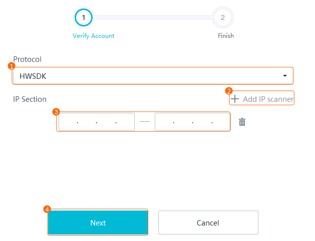
- Set a network segment, as shown in Figure 3-80.
Table 3-55 describes the parameters.
Table 3-55 Parameter descriptionParameter
Description
Protocol
Protocol. Select HWSDK.
IP Section
Start and end IP addresses of the cameras. A specified network segment will shorten the search time.
- The system supports multiple network segments, which can be on different VLANs.
- If you do not set any network segments, the system can search for only cameras whose IP addresses are in the same network segment as the IP address of the local server.
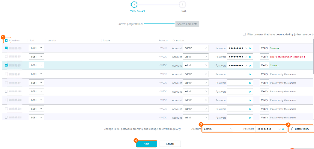
- Verify accounts, as shown in Figure 3-81.
Table 3-56 describes the parameters and buttons.
Table 3-56 Parameter/Button descriptionParameter/Button
Description
Remarks
Port
- If the cameras use the encrypted transmission protocol TLS, set this parameter to 6061.
- If the cameras use a non-encrypted transmission protocol, set this parameter to 6060.
Non-encrypted transmission protocols may cause security risks. You are advised to use an encrypted transmission protocol.
If any camera fails to be connected, rectify the fault by referring to Failure to Verify a Camera When You Follow the Wizard to Add It.
Account
User name and password for registering a camera through the HWSDK protocol.
Password
Batch Verify
Button for verifying the user names and passwords of cameras in batches.
If the verification is successful, a success message is displayed. If the verification fails, a message is displayed, indicating that the camera user name or password is incorrect.
If such a message is displayed, correct the user name or password. Click Verify after modifying information.
Verify
Button for verifying the user name and password of a camera.
- Click Finish.
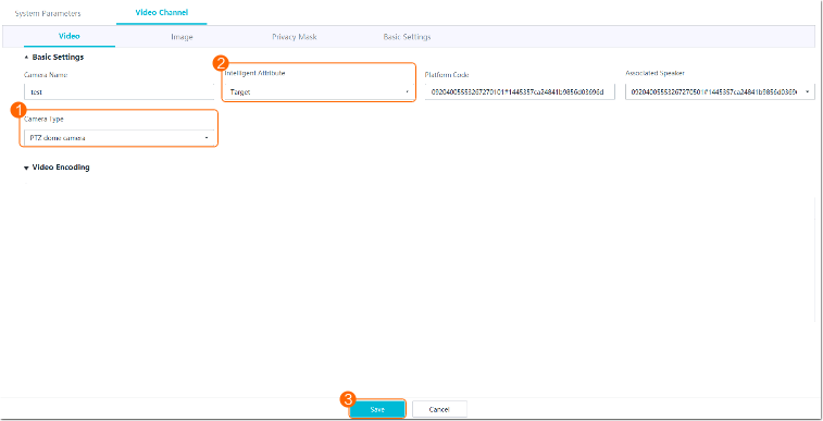
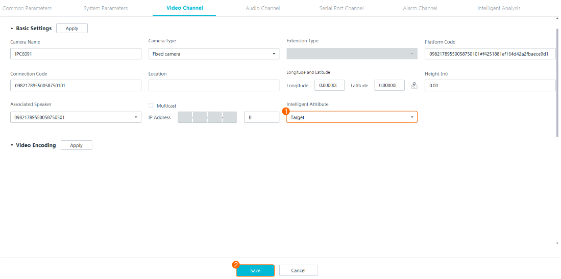
- Set the intelligent attribute and type of a camera.
- Choose .
- Select a desired HWT-IVS1800.
- Right-click the camera for which you want to set the intelligent attribute and type and choose Configure from the shortcut menu.
- Choose Video Channel > Video.
- Set the type and intelligent attribute of the camera, as shown in Figure 3-82.
Table 3-57 describes the mandatory parameters.
Table 3-57 Parameter descriptionParameter
Description
Camera Type
Camera type.
- Fixed camera
- PTZ box camera
- PTZ dome camera
- Fixed dome camera
- Bullet camera
The value of this parameter must be the same as the actual camera type. Otherwise, some basic functions of the camera will be unavailable. For example, if you set this parameter to Fixed camera for a PTZ dome camera, the PTZ function of the camera will be unavailable.
Intelligent Attribute
Intelligent attribute of a camera. The intelligent attribute of a checkpoint camera must be the same as the actual intelligent attribute. Otherwise, snapshots taken by the checkpoint camera cannot be uploaded to the HWT-IVS1800.
This parameter does not need to be set for generic cameras.
- Common (default value)
- Target
- Plate analysis
- Object classification (vehicle + person)
- Person
- Plate analysis + target detection
- Target + person
- Object classification + target
- Other intelligent functions
Connecting Cameras by Device IP Address
This section describes how to connect cameras one by one on the iClient S100.
Context
- Currently, only cameras connected to the HWT-IVS1800 through HWSDK support frontend intelligence configuration.
- In the HWSDK- (passive registration), ONVIF-, and HWSDK_EXt1-compliant access scenarios, cameras with the same IP address and port number cannot be added.
- In the RTSP-compliant access scenario, cameras with the same URL cannot be added.
- OSD cannot be configured for third-party cameras connected through GB/T 28181.
- Only IPv6 cameras connected through ONVIF are supported. You can request streams from such cameras.
Procedure
- Confirm with the camera vendor whether only the MD5 algorithm is supported if ONVIF or RTSP is used for camera connection.
- If not, go to the next step.
- If so, ensure that the MD5 algorithm has been enabled on the device.
- Log in to the OMU portal as the admin user. ( Logging In to the OMU portal)
- Choose System > Advanced Configuration.
- Select OCG from the Module drop-down list box and click Search.
- Set Value for EnableMD5_N_Onvif to 1 to enable the MD5 algorithm for ONVIF connection.
Using the MD5 algorithm may cause cyber security risks. Therefore, perform cyber security controls after enabling this algorithm.
- Log in to the OMU portal as the admin user. (
- Choose Maintenance Management > Video Device > Device List on the iClient S100 home page.
- Click Add in the upper right corner. Alternatively, right-click an HWT-IVS1800 to which you want to connect cameras, and choose Camera Access from the shortcut menu. The Device Access page is displayed.
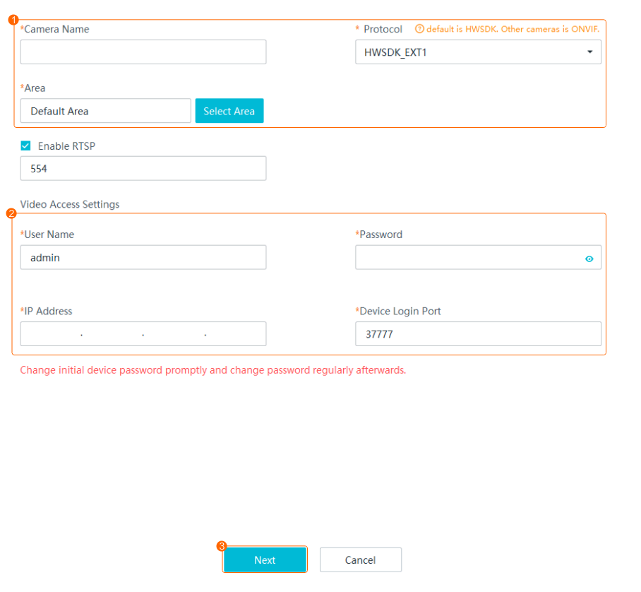
- Select IP Access and click Start.
- Set the parameters for connecting a camera. Table 3-58 describes the parameters.Table 3-58 Parameters for manually connecting a camera
Parameter
Description
Device Name
Camera name displayed on the iClient S100. You are advised to enter the installation location or area of the camera.
Protocol
Protocol used to connect a camera.
NOTE:- You are advised to connect cameras to the HWT-IVS1800 through HWSDK for the configuration and operation of intelligent services. ONVIF allows configuration and operation only for non-intelligent services such as live video viewing and recording playback.
- If you change the password of a camera connected through RTSP on the iClient S100, the connection password in the camera web system will not be changed accordingly.
- When a camera is connected to the IVS1800 through RTSP, the video parameters modified on the LDU or iClient S100 do not take effect. You need to modify the video parameters on the camera side.
Area
Area to which a camera belongs. If no area is specified, the camera belongs to the default area.
The value of Area has been set under Maintenance Management > Basic Management > Area Settings on the iClient S100. (You can configure an area by referring to in the iClient S100 User Guide.)
Only users granted permissions on an area can perform operations on devices in this area.
Connection Code
This parameter can be set only when cameras are connected through GB/T 28181.
The value must be the same as that of Device ID for cameras or SIP Authentication ID for Hikvision cameras. The eleventh to thirteenth digits must be 132.NOTE:The connection code must be a 20-digit integer. Insufficient digits are padded with 0. The code of each device must be unique.
Enable RTSP
Indicates whether to enable RTSP, which can be set only when cameras are connected through HWSDK_EXt1.
After the RTSP stream obtaining function is enabled, live streams are directly transferred from cameras to the iClient S100 without being processed or forwarded by the MU, reducing the system pressure.
To enable the RTSP stream obtaining function, you must set the same port (default port: 554) for the client and the frontend device.
User Name/Password
Registration user name (admin by default) and password used to connect a camera to the device.
For HW cameras, the navigation path of the registration password in the camera web system varies depending on the protocol.
- HWSDK: Choose . On the SDK Password tab page, the value of Current password is the registration password.
- ONVIF: Choose . On the ONVIF Password tab page, the value of Current password is the registration password.
- GB/T 28181: Choose Settings > Network > Platform Connection > Second Protocol Parameters. On the T28181 tab page, the value of Password is the registration password.
IP Address
IP address of a camera.
Device Login Port
Port number for camera access. The value must be the same as that set on the camera side. You are advised to use the default port number. If the port number is changed on the camera side, set this parameter to the actual port number. If the port number is 6061, the camera may fail to be added because the time difference between the camera and the IVS1800 is large. In this case, rectify the fault by referring to Configuring Time Synchronization from a Camera to the HWT-IVS1800.
NOTICE:- If the HWSDK protocol is used for camera registration, set the port number to 6061. Then, messages are encrypted after the camera is connected, improving transmission security.
- If you change the port number after a camera is connected, the camera will be disconnected and reconnected within 1–5s. The reconnection duration depends on the network conditions.
- Click Finish.
- Perform follow-up configurations listed in Table 3-59.Table 3-59 Follow-up configurations
Scenario
Where to Configure
Configuration
Connecting cameras through GB/T 28181
Camera web system
Set parameters for camera connection. For details, see Configuring Connection Through GB/T 28181 in the Camera Web System.
Connecting cameras through ONVIF
Camera web system
Set parameters for camera connection. For details, see Configuring Connection Through ONVIF in the Camera Web System.
Grouping cameras
Add cameras to a group to facilitate camera management.
Configuring areas
Click an online HWT-IVS1800, select one or more cameras, and click
 to adjust the area to which the cameras belong.
Connecting Cameras by Importing a Template
This section describes how to manually connect cameras in batches on the iClient S100.
Context
- In the HWSDK-compliant (passive registration), ONVIF-compliant, and Dahua camera access scenarios, cameras with the same IP address and port number cannot be added.
- If NAT networking is used between the HWT-IVS1800 and camera, you need to set advanced parameter ONVIF_NAT to 1 before importing ONVIF-compliant cameras. For details, see Setting Advanced Parameter ONVIF_NAT.
- In the RTSP-compliant access scenario, cameras with the same URL cannot be added.
- OSD cannot be configured for third-party cameras connected through GB/T 28181.
- Only IPv6 cameras connected through ONVIF are supported. You can request streams from such cameras.
Procedure
Before connecting cameras in batches, you need to fill in the template provided by the system. After importing the completed template, you can connect cameras in batches on the device management page.
- The number of cameras to be connected in batches using a template cannot exceed the maximum number of cameras supported by an HWT-IVS1800. The excess cameras will fail to be connected.
- To connect primary cameras in the 1 + N solution by template, perform the following steps:
Specify the model for each primary camera in the template. The system reserves 1 + N (number of secondary cameras) channels for each of them. After the template is imported, the number of occupied channels equals the number of reported channels of online primary cameras plus the number of channels reserved for offline primary cameras.
If the number of secondary cameras connected to a primary camera is less than N, idle channels will be available after these cameras go online. Then you can import more cameras in batches.
- Choose Maintenance Management > Video Device > Device List on the iClient S100 home page.
- Click Add in the upper right corner. Alternatively, right-click an HWT-IVS1800 to which you want to connect cameras, and choose Camera Access from the shortcut menu. The Device Access page is displayed.
- Select File Import and click Start.
- Click Export Template to download the Device Batch Import.xlsx file to the local computer.
- Open the Device Batch Import.xlsx file and fill in required sheets in the file by referring to Table 3-60 and Table 3-61.
In Table 3-60, M indicates mandatory, O indicates optional, and - indicates not required or involved.
Table 3-60 Parameters in the batch import templateParameter
HWSDK (Recommended)
ONVIF
GB/T 28181
Camera Name
M
M
M
Vendor
M
O
-
Device Form Type
M
M
M
Device Model
O
O
-
Main Device Code
M
M
M
Connection Code
-
-
M
IP Address
M
M
-
Port
M
M
-
User Name
M
M
-
Password
M
M
M
Table 3-61 Parameters in the templateParameter
Description
Camera Name
Camera name displayed on the iClient S100. You are advised to enter the installation location or area of the camera.
Vendor
Camera vendor.
Device Form Type
Camera type. Set this parameter to IPC.
Device Model
Camera model.
Main Device Code
Code of the main device. Enter the code obtained from the Guidance sheet in the template.
IP Address
IP address of a camera.
Port
Port number for camera access. The value must be the same as that set on the camera side. You are advised to use the default port number. If the port number is changed on the camera side, set this parameter to the actual port number.
NOTICE:- If the HWSDK protocol is used for camera registration, set the port number to 6061. Then, messages are encrypted after the camera is connected, improving transmission security.
- If you change the port number after a camera is connected, the camera will be disconnected and reconnected within 1–5s. The reconnection duration depends on the network conditions.
User Name/Password
Registration user name (admin by default) and password used to connect a camera to the device.
For HW cameras, the navigation path of the registration password in the camera web system varies depending on the protocol.
- HWSDK: Choose . On the SDK Password tab page, the value of Current password is the registration password.
- ONVIF: Choose . On the ONVIF Password tab page, the value of Current password is the registration password.
- Port number:
When connecting a camera through ONVIF, you do not need to change the port number. When connecting a camera through HWSDK, you are advised to set the port number to 6061. Then, after the camera is connected, messages are encrypted for transmission, improving information transmission security. In addition, you can configure intelligent services for cameras connected only through port 6061. Some cameras connected through port 6060 support only basic functions, such as live video viewing and recording playback.
- User name and password for registering a camera:
If the registration password of a camera is changed, do not consecutively click Verify. If you click Verify for five or more consecutive times, the iClient S100 will be locked. If the iClient S100 is locked, you cannot connect the camera again until the iClient S100 is unlocked or the camera is restarted.
- Import the completed template file. You can click Browse and select the file, or drag the file from the local path to the Drag file here area on the Manual Batch Access page.
Cameras to be connected are displayed on different tab pages based on their protocols.
- Click Next. The camera connection result is displayed.
- Click Finish.
- Perform follow-up configurations listed in Table 3-62.Table 3-62 Follow-up configurations
Scenario
Where to Configure
Configuration
Connecting cameras through GB/T 28181
Camera web system
Set parameters for camera connection. For details, see Configuring Connection Through GB/T 28181 in the Camera Web System.
Connecting cameras through ONVIF
Camera web system
Set parameters for camera connection. For details, see Configuring Connection Through ONVIF in the Camera Web System.
Grouping cameras
Add cameras to a group to facilitate camera management.
Configuring areas
Click an online HWT-IVS1800, select one or more cameras, and click
 to adjust the area to which the cameras belong.
Connecting Cameras to the HWT-IVS1800
Configuring Connection Through GB/T 28181 in the Camera Web System
When the GB/T 28181 protocol is used to connect a camera to the platform, you need to set the connection parameters in the camera web system.
Prerequisites
- You have prepared a trusted network. The GB/T 28181 protocol uses MD5 digest authentication. The MD5 is a weak algorithm, which does not encrypt signaling or media streams for transmission. Therefore, the protocol must be used on a trusted network to prevent security risks.
- You have obtained the values of the parameters (for example, device ID) for connecting cameras to the HWT-IVS1800 through the GB/T 28181 protocol.
Setting the System Time
To connect a camera to the platform through the GB/T 28181 protocol, ensure that the camera is time-synchronized with the NTP server.
- Open a web browser, enter the camera IP address in the address box, and press Enter.
- Enter the user name and password of the camera and click the login button to log in to the camera web system.
- Choose Settings > System > Time.
- On the Time page, configure NTP time calibration, as shown in Figure 3-83. Table 3-63 describes the parameters.
- Click Save.

Setting GB/T 28181 Parameters
- Log in to the camera web system and choose Settings > Network > Platform Connection.
The Platform Connection page is displayed.
- Click Second Protocol Parameters. Click the T28181 tab. On the tab page that is displayed, select GB/T 28181 to enable the GB/T 28181 protocol.
- Set GB/T 28181 parameters, as shown in Figure 3-84. Table 3-64 describes the GB/T 28181 parameters.
Table 3-64 GB/T 28181 parameters
Parameter
Description
GB/T 28181
If this parameter is selected, the GB/T 28181 protocol is enabled.
Protocol
Protocol. You can select a value from the drop-down list box.
NOTE:If TCC-VMS-2020 is selected, the active and standby servers can be configured. When the active (standby) server fails, services are automatically switched to the standby (active) server.
GB/T 28181 Advanced Parameters
Max recordings can be queried
Maximum number of recordings carried in a packet during recording query when GB/T 28181 is used for platform connection.
The value is an integer ranging from 1 to 20. The default value is 10. If the HWT-IVS1800 limits the packet size, you can properly adjust the value of this parameter. Adjusting the value of this parameter affects the recording query speed.
Compatibility Parameters
H.265
If this parameter is selected, the H.265 and H.264 encoding protocols are supported when the camera is connected to the HWT-IVS1800 through the GB/T 28181 protocol.
If this parameter is not selected, only the H.264 encoding protocol is supported when the camera is connected to the HWT-IVS1800 through the GB/T 28181 protocol.
Clear media streams triggered by same subject
If this parameter is selected, only one channel of video streams can be obtained if the HWT-IVS1800 requests video streams with the same subject ID.
If this parameter is not selected, multiple channels of video streams can be obtained if the HWT-IVS1800 requests video streams with the same subject ID.
Shanghai Local Standard
If this parameter is selected, the Shanghai local protocol is supported.
NOTE:If the Shanghai local standard is enabled, the image capture function of the HWT-IVS1800 does not take effect.
Video stream type
Video stream type. You can select a value from the drop-down list box.
- Auto: Sends media streams based on the request of the HWT-IVS1800.
- Video stream: Sends only video streams.
- Hybrid stream: Sends video and audio streams.
Signaling transmission mode
Signaling transmission mode. The options include UDP and TCP. Only UDP can be selected for cameras to be connected to the HWT-IVS1800.
Service Parameters
Downlink voice stream for voice intercom
Protocol of downlink voice streams for voice intercom. The value can be UDP or TCP.
NOTE:If a camera and the HWT-IVS1800 are on different network segments, you are advised to set this parameter to TCP.
Max. timeouts
If the number of consecutive heartbeat timeouts reaches the value specified by this parameter, the camera cannot connect to the HWT-IVS1800.
The default value 3 is recommended.
NOTE:The maximum number of timeouts for the camera and HWT-IVS1800 must be the same.
Registration validity period (s)
Validity period of the camera registration with the HWT-IVS1800. The default value is 86400 (one day).
NOTE:- If the camera fails to be registered within 86400s, the registration fails. You are advised to use the default value.
- Before the validity period expires, the camera initiates a registration request to the HWT-IVS1800 again.
Heartbeat interval (s)
Time interval at which the camera sends heartbeat messages. The default value 60 is recommended.
NOTE:The camera and the HWT-IVS1800 must have the same heartbeat interval.
Server Parameters
Server IP
HWT-IVS1800 IP address.
Port number
Port used by the HWT-IVS1800 to listen on cameras connecting to the HWT-IVS1800 through GB/T 28181. The default value is 5060.
Before selecting the Port number check box, ensure that the configured port is within the range of 1 to 65535.
Server code
GB/T 28181 server code. The value is a string of 1 to 64 characters, including letters and digits.
NOTE:If a camera is to be connected to the HWT-IVS1800, the eleventh to thirteenth digits of the server code must be 200. The local domain code does not need to be configured for the HWT-IVS1800.
SIP server domain
Domain name, which is a string of up to 127 digits.
Device Parameters
Device ID
Unique ID of a camera. The value contains 1–64 characters, including letters and digits. The value must be the same as the camera ID configured on the HWT-IVS1800.
NOTE:- This parameter is mandatory. If this parameter is not set, service alarms cannot be reported to the HWT-IVS1800.
- If a camera is to be connected to the HWT-IVS1800, the eleventh to thirteenth digits of the device ID must be 132. Besides, the device ID must be different from the lens ID. Otherwise, you cannot view live video from the camera on the HWT-IVS1800.
Password
Password used by a camera to register with the HWT-IVS1800.
NOTE:The value of this parameter must be the same as the registration password configured on the HWT-IVS1800. If they are different, the camera will fail to connect to the HWT-IVS1800.
Name
Login name used for registering a camera with the HWT-IVS1800. The value can contain digits or other characters.
Local port
Port number of the camera for connecting to the SIP server.
NOTE:The value is an integer ranging from 1024 to 65535.
Alarm input ID
Alarm input ID of the camera. The value is a string of 0 to 64 characters, including letters and digits.
NOTE:You need to manually enter the value. The eleventh to thirteenth digits must be 134. Otherwise, the HWT-IVS1800 cannot report alarms properly.
Audio output ID
Audio output ID of the camera. The value is a string of 0 to 64 characters, including letters and digits.
NOTE:You need to manually enter the value. The eleventh to thirteenth digits must be 137. Otherwise, the HWT-IVS1800 cannot transmit uplink or downlink audio streams properly.
Authentication mode
- SHA256: Only the SHA256 authentication method is supported.
- MD5/SHA256: Both MD5 and SHA256 authentication methods are supported.
NOTE:- The MD5 authentication method has security risks. Therefore, you are advised to use the SHA256 authentication method.
- The value of this parameter must be the same as that configured on the HWT-IVS1800. Otherwise, the registration fails.
Channel Parameters
Channel
Channel type of the camera.
Stream index
Type of streams to be sent to the platform. You can select the primary stream or a secondary stream. The default value Primary stream is recommended.
Lens ID
Lens ID. The value is a string of 0 to 64 characters, including letters and digits.
For a multi-lens camera, you need to select a channel type from the drop-down list box and set a unique ID for each lens.
NOTE:If a camera is to be connected to the HWT-IVS1800, the eleventh to thirteenth digits of the lens ID must be 131 or 132. Besides, the device ID must be different from the lens ID. Otherwise, live video from the camera cannot be viewed on the HWT-IVS1800.
- Click Save.

Configuring Connection Through ONVIF in the Camera Web System
When the ONVIF protocol is used to connect a camera to the HWT-IVS1800, you need to set the connection parameters in the camera web system.
Prerequisites
- You have prepared a trusted network. The ONVIF protocol uses MD5 digest authentication, which is a weak algorithm that does not encrypt media streams for transmission. Therefore, the protocol must be used on a trusted network to prevent security risks.
- If the ONVIF protocol needs to use the H.265 encoding protocol, both the ONVIF-compliant camera and the HWT-IVS1800 must support the H.265 encoding protocol. The camera must be of V200R003C10 or later versions. As for the HWT-IVS1800, contact the vendor to obtain the protocol support information. If the camera or platform does not support H.265, set the encoding protocol of video streams (including the primary stream and secondary streams) to H.264 and then set parameters in the camera web system. The detailed procedure is as follows: Log in to the camera web system, choose Settings > Video/Audio/Image > Video, and set Encoding protocol to H.264.
- By default, the ONVIF protocol uses HTTP/HTTPS for transmission.
- The ONVIF protocol supports only the G.711μ audio encoding format.
- If you use the ONVIF protocol to connect a camera to the HWT-IVS1800, the default port number is 80.
Procedure
- Log in to the camera web system (https://Camera IP address).
- Choose Settings > Network > Platform Connection.
The Platform Connection page is displayed.
- Choose Second Protocol Parameters > ONVIF to access the page for setting ONVIF parameters.
- Set ONVIF parameters, as shown in Figure 3-85. Table 3-65 describes the ONVIF parameters.
Table 3-65 ONVIF parameter description
Parameter
Description
Enable media stream keep-alive
Indicates whether to enable the keep-alive function for media streams. To enable the function, select Enable media stream keep-alive.
After the keep-alive function is enabled for media streams, the camera stops sending media streams if it does not receive keep-alive packets sent by the HWT-IVS1800 within a specified period. If the platform supports the keep-alive function, you are advised to enable this function.
Keep-alive duration
Duration that the camera and HWT-IVS1800 keep alive connections for media streams. The value is an integer ranging from 10 to 120, in seconds. For example, if this parameter is set to 60s, the camera does not stop sending media streams even if it does not receive media keep-alive packets within 60s and stops sending media streams if it does not receive media keep-alive packets for more than 60s.
Enable ONVIF
Indicates whether to enable the ONVIF protocol.
Validity period
Indicates whether to enable the ONVIF message validity period function.
After this function is enabled, an ONVIF message will become invalid when the specified validity period elapses.
NOTE:This function is valid only when being supported by the HWT-IVS1800 platform. If the platform does not support this function but this parameter is selected, the camera will fail to connect to the platform. This function is disabled by default. You are advised to enable this function only when security risks exist.
ONVIF metadata flow switch
Indicates whether to obtain metadata from the camera. If this parameter is deselected, only video and audio streams can be obtained.
This function is enabled by default.
Stream type
Stream transmission type. You can select one of the following options from the Stream type drop-down list box:
- Elementary stream: uses the ES compression mode.
- Program stream: uses the PS compression mode.
NOTE:- Select a proper stream transmission type based on the decoder requirements.
- The ONVIF media stream can be configured only when the camera is connected to the platform through the ONVIF protocol.
Authentication mode
Authentication method. You can select one of the following options from the Authentication mode drop-down list box:
- Digest_MD5: digest authentication with MD5 encryption.
- Digest_SHA256: digest authentication with SHA256 encryption.
- Digest_MD5/Digest_SHA256: Both Digest_MD5 and Digest_SHA256 authentication methods are supported.
- Digest_MD5(priority)/WSSE: Both Digest_MD5 and WSSE authentication methods are supported, but Digest_MD5 authentication is preferred.
- WSSE (Web Service Security): WSSE authentication method.
- None: No authentication is performed.
NOTE:- The ONVIF WSSE authentication method has security risks.
- When some platforms to which the cameras connect support ONVIF WSSE authentication only, use the Digest_MD5(priority)/WSSE authentication method.
- When all platforms to which the cameras connect support ONVIF WSSE authentication only, use the WSSE authentication method.
- You are advised to enable the WSSE authentication method when some platforms cannot correctly process Digest messages.
- Security risks may exist when you select None. It is recommended that this authentication method be enabled only when the platform does not support authentication. If None is selected, the system does not perform authentication if you request live video through the RTSP or ONVIF protocol.
Version
ONVIF version supported by the camera. The value must be consistent with the ONVIF version supported by the platform.
ONVIF Trans Protocol Type
ONVIF transmission protocol.
- HTTP/HTTPS: Data is transmitted through HTTP or HTTPS.
- HTTP: Data is transmitted through HTTP.
- HTTPS: Data is transmitted through HTTPS.NOTE:
HTTP is an insecure protocol and has security risks. Therefore, exercise caution when using this protocol.
Password Management
Method 1:
- Click Password Management to expand the Password Management area.
- Set Web user password, New password, and Confirm password.
- Click Save.
Method 2:
- Choose Settings > System > Password Management.
- Click Protocol Password.
- Set Web user password, New password, and Confirm password.
- Click Save.
NOTE:- The default user name is admin. The value of Web user password must be the same as the password of the admin user who logs in to the camera web system.
Change the ONVIF password for data security purposes.
If the ONVIF protocol is used to connect a camera to the HWT-IVS1800, the password of the user (admin by default) used by the HWT-IVS1800 must be the same as that specified in this area. Otherwise, the camera cannot be connected to the HWT-IVS1800. If the authentication fails for 20 consecutive times, the user account will be locked for 5 minutes. After you change the password, keep the new password safe.
- For security purposes, the password must consist of 8 to 20 characters and contain at least two types of the following: uppercase letters, lowercase letters, digits, and special characters.

Connecting a Specific Camera
- After cameras are connected, you are advised to configure the cameras on the LDU or iClient S100. If you configure the cameras in the camera web system, camera configurations on the iClient S100 and in the camera web system may be inconsistent.
- Only compatible cameras can be connected. For details about compatible cameras, see the HWT-IVS1800 Compatibility List.
Connecting a Dual-Lens PTZ Dome Camera
Context
A dual-lens PTZ dome camera consists of a prime lens and a zoom lens. After the camera is connected, each lens occupies one channel.
Procedure
- Connect a dual-lens PTZ dome camera on the iClient S100. For details about the connection modes, see (Recommended) Connecting Cameras by Search.
Connecting a Compound-Eye Camera
Context
A compound-eye camera consists of a prime lens and one or two zoom lenses. After the camera is connected, each lens occupies one channel.
Procedure
- Connect a compound-eye camera on the iClient S100. For details about the connection modes, see (Recommended) Connecting Cameras by Search.
Connecting a 5G Camera
Prerequisites
NAT has been configured.
- If the camera is on an intranet and the HWT-IVS1800 is on an extranet, see Cameras on an Intranet and HWT-IVS1800 on an Extranet.
- If the camera and HWT-IVS1800 are on different intranets, see Cameras and HWT-IVS1800 on Different Intranets.
Procedure
- Connect a 5G camera on the iClient S100. For details about the connection modes, see (Recommended) Connecting Cameras by Search.
Connecting 1 + N Cameras
Context
The high-performance camera (primary camera) performs intelligent analysis on video from generic cameras (secondary cameras) and generates intelligent analysis results.
Prerequisites
The 1 + N cameras have been configured in the camera web system.
Procedure
Connect the 1 + N cameras on the iClient S100. For details about the connection modes, see (Recommended) Connecting Cameras by Search.
Connecting Thermal Cameras
Model Restrictions
Only DH-TPC-BF5421, U1-4R(4)A-Th, U6-4R(40x)A-Th, and DHI-TPC-SD5441-T thermal cameras are supported.
Context
- A thermal camera consists of a common lens and an infrared lens. After the camera is connected, each lens occupies one channel.
- In the Dahua camera access scenario, cameras with the same IP address and port number cannot be added.
- Cameras connected through HWSDK_EXt1 do not support automatic camera type identification. You need to manually change the camera type. For details, see 6.
Prerequisites
You have obtained the SDK files libdhnetsdk.so and libdhconfigsdk.so of the thermal camera.
You can click here to obtain them.
Procedure
- Enable the temperature reporting and snapshot taking functions of the thermal camera.
For details about how to enable the functions, see the camera documentation.
- Load the SDK files.
- Log in to the operating system as the root user. (
 How Do I Log In to the Operating System Through a Network Port?)
 - Upload the SDK files libdhnetsdk.so and libdhconfigsdk.so to the /tmp directory.
- Move the SDK files to the specified directory.
mv /tmp/libdhnetsdk.so /home/lib/ivs_dcg/third/lib/Dahua/arm/
mv /tmp/libdhconfigsdk.so /home/lib/ivs_dcg/third/lib/Dahua/arm/
- Change the SDK file owner group and permissions.
chown ivs_dcg:ivs /home/lib/ivs_dcg/third/lib/Dahua/arm/*
chmod 440 /home/lib/ivs_dcg/third/lib/Dahua/arm/*
- Re-load the library path.
ldconfig
- Restart the DCG process.
sh /home/ivstool/bin/service.sh restart dcg
- Log in to the operating system as the root user. (
- Enable the Basic authentication and the MD5 algorithm.
- Log in to the OMU portal as the admin user. ( Logging In to the OMU portal)
- Choose .
- Select Advanced.
- In the MD5 Algorithm area, select Enable MD5 when RTSP requests media streams from cameras.
Using the MD5 algorithm may cause cyber security risks. Therefore, perform cyber security controls after enabling this algorithm.
- Enable Basic authentication.
- Log in to the OMU portal as the admin user. (
- Connect a camera.
- On the iClient S100 home page, choose .
- Right-click a certain HWT-IVS1800 and choose Add Camera from the shortcut menu.
- Select IP Access and click Start.
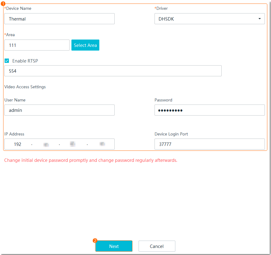
- Set camera parameters, as shown in Figure 3-86.
Table 3-66 describes the key parameters.
Table 3-66 Parameter descriptionParameter
Description
Device Name
Camera name displayed on the iClient S100. You are advised to set this parameter to the installation location or detection area.
Protocol
Access protocol of the camera. Set this parameter to HWSDK_EXt1.
Area
Area to which a camera belongs. If no area is specified, the camera belongs to the default area.
You can configure an area by referring to in the iClient S100 User Manual.
Enable RTSP
RTSP is a client/server application-level protocol for controlling real-time data transmission.
The Enable RTSP check box is selected by default.
User Name
Registration user name and password used to connect a camera to the device.
Password
IP Address
IP address of a camera.
Device Login Port
Camera access port. The port configured in the HWT-IVS1800 must be the same as that on the device. You are advised to use the default port number. If the port number is changed on the camera side, set this parameter to the actual port number.
- Click Finish.
- Set the intelligent attribute of the camera.
- Choose .
- Select an HWT-IVS1800, right-click a camera, and choose Configure from the drop-down menu.
- Choose Video Channel > Video.
- Set Intelligent Attribute to Target detection, as shown in Figure 3-87.
- Set the camera type.
- Right-click a camera in the device list and choose Configure from the shortcut menu.
- Choose .
- Set Camera Type based on the actual camera model.Figure 3-88 Basic Settings area

Verification
- On the iClient S100 home page, choose .
Two video channels are displayed in the device list of the HWT-IVS1800, and the camera is connected successfully.
- Common video channel: The channel name is Device access name.
- Thermal video channel: The channel name is in Device access name 0102 format.
Connecting a Thermal Imaging Camera
Model Restrictions
Only the IPC6021-TH06-DU, U1-4R(4)A-Th, U6-4R(40x)A-Th, and DHI-TPC-SD5441-T thermal cameras are supported.
Context
- A thermal camera consists of a common lens and an infrared lens. After the camera is connected, each lens occupies one channel.
- In the Dahua camera access scenario, cameras with the same IP address and port number cannot be added.
- Cameras connected through HWSDK_EXt1 do not support automatic camera type identification. You need to manually change the camera type. For details, see 5.
Prerequisites
- U6-4R(40x)A-Th, U1-4R(4)A-Th, IPC6021-TH06-DU, and DHI-TPC-SD5441-T cameras can be connected through HWSDK_EXt1. Before the connection, you have obtained the SDK files libdhnetsdk.so and libdhconfigsdk.so of the camera to connect. You can click here to obtain them.
- U1-4R(4)A-Th cameras can be connected through ONVIF.
Procedure
- Enable the temperature reporting function of the thermal imaging camera.
- Log in to the thermal camera's web system.
- Choose .
- Configure a temperature measurement rule, as shown in Figure 3-89.
On the Heat page, you need to set Snapshot to 1. Otherwise, alarms cannot be reported.
- Load the SDK files if the HWSDK_EXt1 protocol is used for access.
- Log in to the operating system as the root user. ( How Do I Log In to the Operating System Through a Network Port?)
- Upload the SDK files libdhnetsdk.so and libdhconfigsdk.so to the /tmp directory.
- Move the SDK files to the specified directory.
mv /tmp/libdhnetsdk.so /home/lib/ivs_dcg/third/lib/Dahua/arm/
mv /tmp/libdhconfigsdk.so /home/lib/ivs_dcg/third/lib/Dahua/arm/
- Change the SDK file owner group and permissions.
chown ivs_dcg:ivs /home/lib/ivs_dcg/third/lib/Dahua/arm/*
chmod 440 /home/lib/ivs_dcg/third/lib/Dahua/arm/*
- Re-load the library path.
ldconfig
- Restart the DCG process.
sh /home/ivstool/bin/service.sh restart dcg
- Log in to the operating system as the root user. (
- Enable the Basic authentication and the MD5 algorithm.
- Log in to the OMU portal as the admin user. ( Logging In to the OMU portal)
- Choose .
- Select Advanced.
- In the MD5 Algorithm area, select Enable MD5 when RTSP requests media streams from cameras.
Using the MD5 algorithm may cause cyber security risks. Therefore, perform cyber security controls after enabling this algorithm.
- Enable Basic authentication.
- Log in to the OMU portal as the admin user. (
- Connect a camera.
- On the iClient S100 home page, choose .
- Right-click a certain HWT-IVS1800 and choose Camera Access from the shortcut menu.
- Select IP Access and click Start.
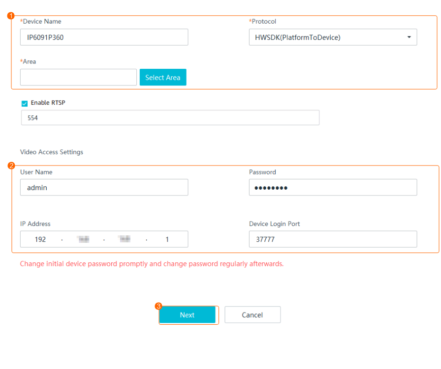
- Set camera parameters, as shown in Figure 3-90.
Table 3-67 describes the key parameters.
Table 3-67 Parameter descriptionParameter
Description
Device Name
Camera name displayed on the iClient S100. You are advised to enter the installation location or detection area.
Driver
Protocol. You can set this parameter to HWSDK_EXt1 or ONVIF as required.
Area
Area to which a camera belongs. If no area is specified, the camera belongs to the default area.
For details about how to configure an area, see in the iClient S100 User Manual.
Enable RTSP
RTSP is a client/server application-level protocol for controlling real-time data transmission.
The Enable RTSP check box is selected by default.
User Name
Registration user name and password used to connect a camera to the device.
Password
IP Address
IP address of a camera.
Device Login Port
Camera access port. The port configured on the HWT-IVS1800 must be the same as that on the camera. You are advised to use the default port number. If the port number is changed on the camera side, set this parameter to the actual port number.
- Set the camera type.
- Right-click a camera in the device list and choose Configure from the shortcut menu.
- Choose .
- Set Camera Type based on the actual camera model.Figure 3-91 Basic Settings area

Verification
- On the iClient S100 home page, choose .
Two video channels are displayed in the device list of the HWT-IVS1800, and the camera is connected successfully.
- Common video channel: The channel name is Device access name.
- Thermal video channel: The channel name is in Device access name 0102 format.
- Choose Complex Applications > Video Alarm > Behavior Analysis Alarm, and view alarms.
Connecting a Panoramic Camera
Model Restrictions
- Only IPC6091-P180-Z40, IPC6092-P360-Z40, and P4-4R(1.4)A panoramic cameras are supported.
- IPC6091-P180-Z40 and IPC6092-P360-Z40 do not support the home position.
Prerequisites
- P4-4R(1.4)A, IPC6091-P180-Z40, and IPC6092-P360-Z40 cameras can be connected through HWSDK_EXt1. Before the connection, you have obtained the SDK files libdhnetsdk.so and libdhconfigsdk.so of the camera to connect. You can click here to obtain them.
- P4-4R(1.4)A, IPC6091-P180-Z40, and IPC6092-P360-Z40 cameras can be connected through ONVIF.
Context
- P4-4R(1.4)A is a fisheye camera. IPC6091-P180-Z40 or IPC6092-P360-Z40 consists of one PTZ dome camera and one panoramic camera. After such devices are connected, each lens occupies a channel.
- In the Dahua camera access scenario, cameras with the same IP address and port number cannot be added.
- Cameras connected through HWSDK_EXt1 do not support automatic camera type identification. You need to manually change the camera type. For details, see 4.
Mode |
Application Scenario |
Remarks |
|---|---|---|
IP Access |
The device can be connected to the network where the IP addresses of the cameras are located. The network cables can be connected to the network ports corresponding to the same VLAN or different VLANs. |
Log in to the camera web system to configure the camera IP address. |
HWSDK_EXt1-based Access
- Load the SDK files.
- Log in to the operating system as the root user. ( How Do I Log In to the Operating System Through a Network Port?)
- Upload the SDK files libdhnetsdk.so and libdhconfigsdk.so to the /tmp directory.
- Move the SDK files to the specified directory.
mv /tmp/libdhnetsdk.so /home/lib/ivs_dcg/third/lib/Dahua/arm/
mv /tmp/libdhconfigsdk.so /home/lib/ivs_dcg/third/lib/Dahua/arm/
- Change the SDK file owner group and permissions.
chown ivs_dcg:ivs /home/lib/ivs_dcg/third/lib/Dahua/arm/*
chmod 440 /home/lib/ivs_dcg/third/lib/Dahua/arm/*
- Re-load the library path.
ldconfig
- Restart the DCG process.
sh /home/ivstool/bin/service.sh restart dcg
- Log in to the operating system as the root user. (
- Add the camera on the .
- On the iClient S100 home page, choose .
- Right-click a certain and choose Camera Access from the shortcut menu.
- Select IP Access and click Start.
- Add a camera, as shown in Figure 3-92.
Table 3-69 describes the key parameters.
Table 3-69 Parameter descriptionParameter
Description
Device Name
Camera name displayed on the iClient S100. You are advised to set this parameter to the installation location or detection area.
Protocol
Access protocol of the camera. Set this parameter to HWSDK_EXt1.
Area
Area to which a camera belongs. If no area is specified, the camera belongs to the default area.
You can configure an area by referring to in the iClient S100 User Manual.
Enable RTSP
RTSP is a client/server application-level protocol for controlling real-time data transmission.
The Enable RTSP check box is selected by default.
User Name
User name and password for logging in to the camera web system.
Password
IP Address
IP address of a camera.
Device Login Port
Camera access port. The port configured in the HWT-IVS1800 must be the same as that on the device. You are advised to use the default port number. If the port number is changed on the camera side, set this parameter to the actual port number.
- Set the intelligent attribute of the camera.
- Choose .
- Select an HWT-IVS1800, right-click a camera, and choose Configure from the drop-down menu.
- Choose Video Channel > Video.
- Set Camera Type to PTZ dome camera and Intelligent Attribute to Other intelligent functions, as shown in Figure 3-93.
- Set the camera type.
- Right-click a camera in the device list and choose Configure from the shortcut menu.
- Choose .
- Set Camera Type based on the actual camera model.Figure 3-94 Basic Settings area

ONVIF-based Access
- The iClient S100 supports connection to IPC6091-P180-Z40 and IPC6092-P360-Z40 cameras through ONVIF. For details, see Connecting a Generic Camera.
Verification
- If the connected camera is of the IPC6091-P180-Z40 or IPC6092-P360-Z40 model, two video channels are displayed in the device list of the HWT-IVS1800, and the camera status is connected.
Video channel of panoramic camera 1: The channel name is in Device access name 0102 format, and IPC is displayed in the lower left corner of the live video image.
Video channel of the PTZ dome camera: The channel name is Device access name, and IP PTZ Dome is displayed in the lower left corner of the live video image.
By default, a recording plan is configured for the video channel of panoramic camera 1. For details about how to configure recording plans for other channels, see Recording Configuration.
Connecting a China Forestry Star Camera
Model Restrictions
Only high-rise dual-spectrum cameras of the FW-500-ET-C10 model are supported.
Context
An FW-500-ET-C10 camera consists of a visible-light optical lens and an infrared lens. After the camera is connected, each lens occupies a channel.
Procedure
Connect an FW-500-ET-C10 camera on the iClient S100 through GB/T 28181. For details about the connection method, see Connecting a Generic Camera.
Connecting a Dahua Common PTZ Dome Camera
Model Restrictions
- Only P5-4RV(4x)A PTZ dome cameras are supported.
- In the Dahua camera access scenario, cameras with the same IP address and port number cannot be added.
Prerequisites
P5-4RV(4x)A cameras can be connected only through HWSDK_EXt1. You have obtained the SDK files libdhnetsdk.so and libdhconfigsdk.so of the camera to connect. You can click here to obtain them.
Procedure
- Load the SDK files.
- Log in to the operating system as the root user. ( How Do I Log In to the Operating System Through a Network Port?)
- Upload the SDK files libdhnetsdk.so and libdhconfigsdk.so to the /tmp directory.
- Move the SDK files to the specified directory.
mv /tmp/libdhnetsdk.so /home/lib/ivs_dcg/third/lib/Dahua/arm/
mv /tmp/libdhconfigsdk.so /home/lib/ivs_dcg/third/lib/Dahua/arm/
- Change the SDK file owner group and permissions.
chown ivs_dcg:ivs /home/lib/ivs_dcg/third/lib/Dahua/arm/*
chmod 440 /home/lib/ivs_dcg/third/lib/Dahua/arm/*
- Re-load the library path.
ldconfig
- Restart the DCG process.
sh /home/ivstool/bin/service.sh restart dcg
- Log in to the operating system as the root user. (
- Add the camera on the .
- On the iClient S100 home page, choose .
- Right-click a certain and choose Camera Access from the shortcut menu.
- Select IP Access and click Start.
- Add a camera, as shown in Figure 3-95.
Table 3-70 describes the key parameters.
Table 3-70 Parameter descriptionParameter
Description
Device Name
Camera name displayed on the iClient S100. You are advised to set this parameter to the installation location or detection area.
Protocol
Access protocol of the camera. Set this parameter to HWSDK_EXt1.
Area
Area to which a camera belongs. If no area is specified, the camera belongs to the default area.
You can configure an area by referring to in the iClient S100 User Manual.
Enable RTSP
RTSP is a client/server application-level protocol for controlling real-time data transmission.
The Enable RTSP check box is selected by default.
User Name
User name and password for logging in to the camera web system.
Password
IP Address
IP address of a camera.
Device Login Port
Camera access port. The port configured in the HWT-IVS1800 must be the same as that on the device. You are advised to use the default port number. If the port number is changed on the camera side, set this parameter to the actual port number.
Verification
- On the iClient S100 home page, choose .
Corresponding video channels are displayed in the device list of the HWT-IVS1800, and the camera is connected successfully.
Configuring the Video and Image Services
Live Video Viewing
Strictly follow your local laws and regulations when using services of this product, for example, recording video, recording voice, and taking snapshots. Do not use them for illegitimate purposes such as infringing on personal privacy or observing employee behavior.
Viewing Live Video from a Single Camera
- Choose on the iClient S100 home page.
- Double-click an online camera in the Devices area or drag the online camera to a live video pane. Then you can view live video from this camera.
During live video viewing, ensure that no window or dialog box of another program overlaps the video pane that is playing live video. Otherwise, artifacts or video stuttering may occur.
If the live network is unstable, frame freezing or artifacts may occur on the live video. In this case, you are advised to enable the bandwidth adaptation function in the camera web system. After bandwidth adaptation is enabled, the camera can decrease or increase the bit rate based on the network condition to ensure smooth live video playing.
Viewing Live Video from Grouped Cameras
- Choose Maintenance Management > Video Device > Group Device on the iClient S100 home page and group cameras.
- Click Add on the right of Group Device List, enter the group name, and click
 .
. - Click the camera group and click Add in the upper right corner. In the dialog box that is displayed, select cameras and click OK, as shown in Figure 3-96.
- Click Add on the right of Group Device List, enter the group name, and click
- Choose on the iClient S100 home page and view live video from cameras in a group (containing more than one camera and excluding cameras in subgroups).
In the device list (for device groups or all devices):
- Hold down Ctrl or Shift, select multiple cameras from the device tree, and drag the cameras to live video panes.
- Drag cameras on the Groups or Devices tab page to live video panes.
- Click
 next to a group on the Groups tab page or next to an IVS1800 on the Devices tab page.
Select Tile or Cycling to start viewing live video from cameras on the Group Device or Device List tab page.- In tile mode:
- Video from selected cameras is played in the camera selection sequence.
- If the number of idle live video panes is less than the number of online cameras in the group, video from some cameras will not be played. You need to manually adjust the video pane layout and view live video.
- Live video can be played in sequence only in the selected video panes. For example, if you drag four cameras to the fourth video pane in the layout of four video panes, live video from the cameras is played in the fourth video pane in sequence, and is not played in the first three video panes even if they are idle.
- In cycling mode:
- Click Advanced and set parameters. Table 3-71 describes the key parameters.
Table 3-71 Key parameters
Parameter
Description
Panes
Number of cycling panes, which must be less than the number of cameras to cycle.
Arrangement
- Tile
- Custom: In the Customize Panes window that is displayed, select panes and click Start.
Interval
Dwell time for selected cameras to play live video, in seconds.
Stream Type
The default value is Primary.
- Click OK to start cycling.
- Click Advanced and set parameters. Table 3-71 describes the key parameters.

Camera Cycling
Application Scenario
You can configure a cycling policy to view live video from multiple cameras at a certain interval. For example, multiple cameras are deployed on Tianmushan Road. However, live video panes are insufficient for playing live video from all cameras at the same time, and therefore it is better to configure a cycling policy to view live video from the cameras at an interval of 30s.
Procedure
- Choose on the iClient S100 home page.
- Click
 in the lower right corner of the page. To add a cycle group for the first time, click +. Otherwise, click New Group.
 - In the New Cycle window, configure cycling group information, as shown in Figure 3-97. Table 3-72 describes the key parameters.
Table 3-72 Key parameters for adding a cycling group
Parameter
Description
Pane Quantity
Number of cycling panes, which must be less than the number of cameras to cycle.
Dwell Time (s)
Dwell time at the selected cameras. The dwell time can be configured for multiple groups in batches or for a single group. In this example, the dwell time is configured for a single group.
Live Stream
- Personal settings: The settings are the same as those in the Personal Settings area.
- Primary: The primary stream of the camera is used. The primary stream features a high bit rate, definition, and bandwidth usage.
- Secondary 1: Secondary stream 1 of the camera is used. The secondary stream features low definition and bandwidth usage.
NOTE:When bandwidth resources are limited, set this parameter to Secondary 1 or Secondary 2.
Video Wall Stream
- Personal settings: The settings are the same as those in the Personal Settings area.
- Primary: The primary stream of the camera is used. The primary stream features a high bit rate, definition, and bandwidth usage.
- Secondary 1: Secondary stream 1 of the camera is used. The secondary stream features low definition and bandwidth usage.
NOTE:When bandwidth resources are limited, set this parameter to Secondary 1 or Secondary 2.
Up/Down
Select a camera and click Up or Down to adjust the camera cycling sequence.
- Click
 in the lower right corner of the Live page. The new cycling group is displayed in the Cycle Cameras window.
- Click
 . The selected pane is regarded as the first pane. Live video from the selected cameras is played in sequence in cycling mode. For example, if pane 2 is selected, and Pane Quantity is set to 3, live video is played in panes 2, 3, and 4 in cycling mode.
 - Click
 to customize panes for live video viewing in cycling mode.
- Click

View Management
Application Scenario
You can save live video pane layout settings (including camera settings) and cycling settings as views to facilitate your later use.
- View favoriting: You are responsible for viewing live video from cameras on Tianmushan Road (four-pane layout) and Xixi Road (nine-pane layout). You can favorite the views to quickly switch between them without repeatedly dragging cameras to live video panes.
- View schedule configuration: You have configured multiple views to save live video from multiple cameras on Xixi Road. You can configure view schedules so that these views can be automatically played in the specified periods every week.
Procedure
- Choose on the iClient S100 home page.
- Select the required live video pane layout. Double-click an online camera in the Devices area or drag the online camera to a live video pane.
You can save cycling views after starting viewing live video in cycling mode. For details about how to configure and start camera cycling, see Camera Cycling. You can then configure a view schedule to perform periodic cycling as scheduled.
- Click
 and set Save As to New or Overwrite.
- If you set Save As to New, set View Name. The new view will be saved.
- If you set Save As to Overwrite, select an existing view from the Overwrite text box. The new view will overwrite the existing one.
- Click OK.
- Repeat 2 through 4 to save more views.
- Click the Favorites tab and view the favorited views in the Favorited Views area.
- Click
 next to Favorited Views. The View Schedule page is displayed.
 - Click New Schedule. In the New Schedule window that is displayed, set view schedule parameters, as shown in Figure 3-98. Table 3-73 describes related parameters.
Table 3-73 Parameter description
Parameter
Description
Cycle
Cycle for executing a view schedule.
Period
Time segment for playing a view.
Drag the mouse to configure a specified time segment for view playing. Right-click the time segment and choose a view from the shortcut menu. Click the time segment and set specific time points.

Snapshot Taking
Manual snapshots are local snapshots. Table 3-74 describes the function of local snapshots.
Snapshot Type |
Function |
|---|---|
Local snapshot |
Local snapshots are taken during live video viewing and stored on the computer where the iClient S100 is located. NOTE:
Do not perform local snapshot taking in an alarm pane, because the alarm pane will play the alarm-triggered live video when the corresponding alarm is generated and interrupt the local snapshot taking. |
Procedure
- Choose on the iClient S100 home page.
- Double-click an online camera in the Devices area or drag the online camera to a live video pane. Then you can view live video from this camera.
- Take a snapshot and save it on the local computer.
Click
 on the toolbar of the live video pane, or right-click the live video pane and choose Snapshot from the shortcut menu to take a snapshot of the current video image.
In this example, use the default storage directory. After the snapshot is taken, the message "Snapshot successful" is displayed in the lower right corner of the client page. You can click Click here to open folder to go to the snapshot storage directory.
- View the snapshot.
View the snapshot stored on the local computer.
Choose Maintenance Management > Local Settings on the iClient S100 home page. You can view the snapshot in the local snapshot storage directory.
OSD Settings
Application Scenario
After setting On-Screen Display (OSD) parameters, you can set whether to display the specified text and time, and whether to enable the text blinking function on the video.
Model Restrictions
OSD cannot be configured for third-party cameras connected through GB/T 28181.
Procedure
- On the iClient S100 home page, choose .
- Double-click an online camera in the Devices area or drag the online camera to a live video pane. Then you can view live video from this camera.
- Right-click a live video pane, choose OSD Settings from the shortcut menu, and set OSD parameters, as shown in Figure 3-99. Table 3-75 describes the parameters.
Table 3-75 OSD parameter description
Parameter
Description
Time Overlay
Indicates whether to display the current camera time on live video images.
Text Overlay
Indicates whether to display texts on live video images. You can select a check box under Text Overlay and enter the text to be displayed in the text box. You are advised to set this parameter to the IP address or installation location of the camera.
NOTE:- To display multiple lines of texts on video images, select multiple check boxes under Text Overlay and enter the texts to be displayed in the text boxes.
- The maximum number of characters is determined by camera capabilities.
- A maximum of 10 OSD records can be added for a camera connected through HWSDK.
Red text box
Allows you to drag the red text box to adjust the display position.

PTZ Controls
Application Scenario
You can perform PTZ controls to control the camera orientation and focal length and invoke preset positions. You can configure preset positions and follow-up tours to periodically view live video of specified sites.
For example, site A is a key area for video detection. To achieve better detection effect, you can perform PTZ controls to adjust the camera orientation and focal length. You can set the adjusted orientation and focal length as a preset position. When you need to detect site A in the future, you can directly invoke the preset position to adjust the camera to the specified orientation and focal length. If you have multiple key areas for video detection, you can set preset positions for each area and configure a tour to periodically view live video of these areas.
Prerequisites
The camera is a PTZ dome camera or a camera of another type providing PTZ functions.
- This section illustrates how to perform PTZ controls using a PTZ dome camera.
- By default, PTZ dome cameras and PTZ box cameras provide all PTZ functions, and bullet cameras and fixed dome cameras only provide some PTZ functions, for example, zoom in or out and adjust focal lengths. The specific functions are subject to those displayed on the PTZ Control page of the iClient S100.
- PTZ controls results vary depending on the specific functions supported by cameras. For details, see the camera compatibility list.
- If you attempt to steer a camera that is performing a tour to a specified preset position, the camera will automatically stop the tour.
Basic Operations
- Choose on the iClient S100 home page.
- Drag an online PTZ camera in the Devices area to a live video pane.
- Click Expand next to PTZ Control in the lower left corner. The PTZ Control panel is displayed, as shown in Figure 3-100.
- Use the eight arrow buttons to rotate a PTZ camera to adjust the camera shooting angle.
Click the expand icon next to Advanced and drag the slider on
 or click
  or
or  to control the PTZ rotation speed.
- Drag the slider leftward or click
 to slow down the PTZ rotation speed.
 - Drag the slider rightward or click
 to speed up the PTZ rotation speed.
- Drag the slider leftward or click
- Click
 or
or  to zoom in or out on the live video image.
 If you zoom in on the video image for more than 30 times, the camera will enter the digital zoom mode. If you set the current position where the camera shoots as a preset position, the camera will not record the digital zoom ratio. When you invoke the preset position, the video image is zoomed in only for 30 times.
- Click a preset position ID in
 to invoke the preset position.
You can set positions where the camera shoots as preset positions. Then you can invoke a preset position to quickly rotate the camera to that position. For details about how to set a preset position, see Configuring Preset Positions and the Home Position.
- Click the expand icon next to Advanced and click buttons in
 in the Advanced area to use other advanced functions of the PTZ device. Table 3-76 describes the related buttons.
Table 3-76 Button description
in the Advanced area to use other advanced functions of the PTZ device. Table 3-76 describes the related buttons.
Table 3-76 Button descriptionButton
Description
3D Positioning
Automatically adjusts the PTZ camera shooting angle and focal length based on the regions of interest (ROIs) on the live video image.
The procedure is as follows:
- Click
 . Hold down the left mouse button and select an ROI on the live video image. The system automatically adjusts the shooting angle and focal length to the optimal using the ROI as the center. If you draw a frame from left to right, the video image within the frame is automatically zoomed in. If you draw a frame from right to left, the video image within the frame is automatically zoomed out.
 - Click
 and click a position on the live video image. The system automatically rotates the PTZ camera to the position.
NOTE:If an ONVIF-compliant device needs to use the 3D zoom-in function, the device must implement the 3D zoom-in function in the same mode as the platform. For details about the mode used by the platform to implement the 3D zoom-in function, contact related engineers.
Illuminator
Click
 to turn on or off the illuminator.
Wiper
Click
 to enable or disable the wiper.
Horizontal Tour
Allows you to view live video from the camera that is performing a horizontal tour.
The horizontal tour function allows unidirectional or back-and-forth scanning in either a clockwise or an anti-clockwise direction at a specified degree (including 360°).
Aperture-
Decreases the aperture of the camera.
Aperture+
Increases the aperture of the camera.
Focus+
Increases the focal length of the camera.
Focus-
Decreases the focal length of the camera.
- Click
- Use the eight arrow buttons to rotate a PTZ camera to adjust the camera shooting angle.
- (Optional) Click
 on the toolbar of the live video pane. Then you can use the mouse to control the PTZ rotation direction.
The operation method is specified by Move Controls under .
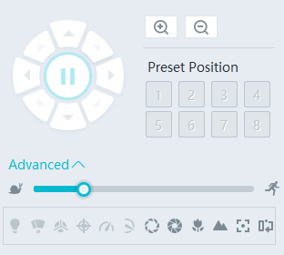
Configuring Preset Positions and the Home Position
A home position is a special preset position to which a PTZ camera automatically rotates if you do not control the rotation direction of the camera within a specified period.
- Click the live video pane of the selected PTZ dome camera, control the PTZ rotation direction and zoom ratio, and rotate the PTZ device to a detection site for which you want to add as a preset position.
- Click the expand icon next to Advanced in the PTZ Control panel and click the Presets tab. The Presets tab page is displayed, as shown in Figure 3-101.
- Click
 . In the Add Preset Position dialog box that is displayed, set Preset Name.
 To edit the name of a preset position, right-click the preset position and choose Edit from the shortcut menu.
- Click OK.
- Repeat 1 through 4 to add more preset positions.
- Click a preset position and click Invoke for the camera to rotate to the preset position.
- Click a preset position and click Set as Home. In the Set as Home dialog box that is displayed, set Wait Time (s) and click OK, as shown in Figure 3-102.If the PTZ camera is not at the home position currently, the PTZ camera automatically rotates to the home position if no PTZ controls are performed before the configured waiting duration elapses.
Right-click a preset position and choose Edit from the shortcut menu. In the Edit Preset Position dialog box that is displayed, select Enable Focus Memory and click OK to enable focus memory. If you deselect Enable Focus Memory, this function is disabled.
- You can invoke a preset position in either of the following ways:
- Click the buttons under Preset Positions to invoke the first eight preset positions.
- Double-click a preset position in the preset position list.


Configuring Tours
- Click the expand icon next to Advanced in the PTZ Control panel and click the Tour tab. The Tour tab page is displayed, as shown in Figure 3-103.
- Click the add button. Add a tour, as shown in Figure 3-104. Table 3-77 describes related buttons and parameters.
Table 3-77 Parameter/Button description
Parameter/Button
Description
Up/Down
Buttons for adjusting the sequence of a selected preset position.
Add
Button for adding preset positions to a tour.
Delete
Button for deleting selected preset positions in batches.
Preset Position
Preset position in a tour. You can click Add and select a preset position from the drop-down list box.
Each tour supports 1 to 20 preset positions.
Dwell Time (s)
Tour duration for each preset position.
NOTE:A short tour duration may shorten the service life of the camera motor and belt. If the preset positions do not need to be frequently switched onsite, you are advised to set the tour duration longer (for example, over 60s).
Speed Level
Tour speed for each preset position.
- Click
 . The camera starts to play live video along the tour.


Recording
Application Scenario
You can record video after cameras are connected to the HWT-IVS1800.
The recording function of the HWT-IVS1800 can be classified into scheduled recording and manual recording, which can be further classified into scheduled server recording and manual local recording. Table 3-78 describes the application scenarios of these recording types.
Recording Type |
Application Scenario |
|
|---|---|---|
Scheduled |
Scheduled server recording |
Scheduled recording is applicable if you need to save video of specified areas on the hard disks of the HWT-IVS1800 to facilitate analysis of incidents or abnormal situations. |
Manual |
Manual local recording |
When emergencies occur in detection areas, you can manually record video and store it to the computer where the iClient S100 is installed. |
Operation Process
Before recording video, you need to determine the recording mode: scheduled recording or manual recording. In addition, you need to store recordings on the hard disks of the HWT-IVS1800 or the computer where the iClient S100 is installed based on the site requirements. Figure 3-105 shows the configuration process.

- Before recording video, you need to set recording parameters, such as the storage policy and video buffering.
- Select scheduled recording or manual recording as required (for details, see Table 3-78) and start recording.
Recording Configuration
Setting Recording Parameters
Configuring a Recording Storage Policy
Before configuring a recording plan or manually recording video, you need to configure a recording storage policy.
If intermittent network disconnection occurs frequently, recording storage period may be affected. If the network is intermittently disconnected for more than 30 seconds each time, recording indexes will be reallocated. A maximum of 20,000 recording indexes are supported. If the number of recording indexes exceeds 20,000, the indexes will be recycled. As a result, recordings will be deleted.
Procedure
- On the iClient S100 home page, choose .
- Right-click a device and choose Storage Management.
- Click the Storage Policy tab. Select a camera in the camera list. Alternatively, click
 , set search criteria, and select the camera whose recording parameters are to be set. The page shown in Figure 3-106 is displayed.
- Set storage policy parameters. Table 3-79 describes the parameters.Table 3-79 Storage policy parameters
Parameter
Description
Storage Mode
Storage mode. Select All frames in this example.
The system stores the complete recordings within the all-frame storage period. When the storage period elapses and the size of available storage space is less than the threshold, the system deletes the earliest recordings.
- If the size of available storage space is greater than the threshold:
- When Video Recycle Policy is set to Recycle by storage space on the OMU portal, the system continues recording video as planned.
- When Video Recycle Policy is set to Recycle by expiration time on the OMU portal:
- If the storage period of some recordings exceeds the all-frame storage period, the system deletes these files in ascending order of their generation time until they are all deleted.
If the storage period of all recordings is within the all-frame storage period, the system continues recording video as planned.
If the size of available storage space is less than or equal to the threshold:
When Insufficient Recording Space Policy of this server is set to Stop if insufficient on the OMU portal:
If the storage period of some recordings exceeds the all-frame storage period, the system deletes these files in ascending order of their generation time.
If the storage period of all recordings is within the all-frame storage period, the system stops recording immediately after the storage space is used up.
When Insufficient Recording Space Policy of this server is set to Overwrite if insufficient on the OMU portal:
Recordings are deleted in the following sequence until the size of available storage space is greater than the threshold: recordings whose storage period has elapsed > recordings whose storage period is not configured > earliest recordings in the storage period.
All Frame Storage (days)
Number of days for storing recordings.
The value ranges from 0 to 9999. A larger value indicates a longer video storage period. The default value is 0.
NOTE:- When this parameter is set to 0, the storage period is not fixed and the storage priority is low. When the storage space is used up, recordings are recycled first.
- After the storage period settings are modified, you must pay attention to the storage data changes. Shortening the storage period will cause loss of the content that is stored in the original storage period but not in the new storage period.
- You are advised to configure the storage period during software deployment.
- You are advised not to change the storage period during the upgrade, key assurance period, or important events.
Alarm-Triggered Recording Storage (days)
(available for alarm-triggered recording)
Manual Recording Storage (days)
(available for manual server recording)
Server Recording Stream
Stream type used for scheduled server recording (stored on the hard disks of the IVS1800). Set this parameter based on the bandwidth and network quality.
The options are as follows:
- Automatic: No stream is specified, and the primary stream is used by default.
- Primary: The primary stream of the camera is used. The primary stream features a high bit rate, image clarity, and bandwidth usage.
- Secondary 1/Secondary 2: Secondary streams of the camera are used. Secondary streams feature low bit rates, image clarity, and bandwidth usage. If the camera has multiple secondary streams, the parameter will have multiple secondary stream options such as Secondary 1 and Secondary 2.
Alarm-Triggered Recording Stream
Stream type used for alarm-triggered recording (stored on the hard disks of the IVS1800).
Pre-recording
Pre-recording mode.
The options are as follows:
No pre-recording (default value): The pre-recording function is disabled.
PU pre-recording: A frontend device records video of several seconds (specified by Pre-recording Duration (s)) before an alarm is triggered, which ensures recording integrity and facilitates analysis of alarm-triggered recordings.
Pre-recording Duration (s)
If Pre-recording is set to PU pre-recording, the frontend device records video of several seconds before an alarm is triggered. The default value is 10 (not configurable).
Save Image
Indicates whether to store images captured by checkpoint cameras. The options are Yes and No.
Image Storage (days)
The default value is 90.
CAUTION:- After the storage period settings are modified, you must pay attention to the storage data changes. Shortening the storage period will cause loss of the content that is stored in the original storage period but not in the new storage period.
- You are advised to configure the storage period during software deployment.
- You are advised not to change the storage period during the upgrade, key assurance period, or important events.
- If the size of available storage space is greater than the threshold:
- Click Save.
- (Optional) Click Apply to Others, select cameras to which the current camera's recording storage policy is to be copied, and click OK.

(Optional) Configuring Video Buffering
When the network is disconnected, cameras can temporarily store scheduled recordings to their SD cards based on the server recording plans. If you have enabled the video buffering function, the platform sends a video buffering request to the cameras after the network is recovered, and then the cameras send the stored video to the server. This ensures video integrity.
Prerequisites
- You have inserted SD cards into cameras that can execute recording tasks properly.
- You have synchronized time between the server and the cameras.
Procedure
- Choose on the iClient S100 home page.
- Double-click a camera for which video buffering needs to be configured in the camera list on the right.
- On the configuration page that is displayed, choose .
- Set Video Buffering to On, as shown in Figure 3-107.
If a camera connected through GB/T 28181 is disconnected from the network for more than 3 minutes, the camera goes offline. After the camera goes online again, video buffering is triggered.
- Click Save.
- On the OMU portal, configure the number of retry days and the number of daily retry times for video buffering.
- Choose on the iClient S100 home page.
- Right-click a device and choose Maintenance.
- In the dialog box that is displayed, click OK. The OMU portal will be automatically opened in the browser.
- On the OMU portal, choose System > Advanced Configuration.
- Set Module name to MU and click Search.
- Click Edit and set MaxUploadRetryCountsLimit and MaxUploadRetryDaysLimit, as shown in Figure 3-108. Table 3-80 describes the parameters.
Table 3-80 Parameter description
Parameter
Description
MaxUploadRetryCountsLimit
Maximum number of times for a camera to send a buffered recording to the platform consecutively even if the sending fails.
Assume that you set this parameter to 3. After the camera goes online again, the system triggers video buffering. If video buffering fails for three consecutive times, the system skips the current recording and proceeds with video buffering of the next recording.
MaxUploadRetryDaysLimit
Number of days for video buffering.
Assume that you set this parameter to 3. When the camera goes online again, the system sends a request to upload buffered recordings of the last three days.
- Click Save.

Configuring Scheduled Recording
Configuring Scheduled Server Recording
The system can record video in a specified time segment and store the recorded video on server disks.
Procedure
- Choose on the iClient S100 home page.
- Right-click a device and choose Storage Management.
- Click the Server Recording Plan tab. The tab page for configuring a server recording plan is displayed.
- Configure server recording plans.
- Configure a server recording plan.
- In the cameras list, select a camera whose recording storage policy has been configured.
- In the Server Recording Plan area on the right, toggle on Enable Recording, as shown in Figure 3-109.
- Drag the timeline to select a time segment for executing the server recording plan.
If you click Continuous, the recording plan will be executed all day and you do not need to specify any time segment.
- Click Save.
- Configure server recording plans in batches.
- After configuring a server recording plan, click Apply to Others.
- Select cameras for which you want to configure the same recording plan in batches, as shown in Figure 3-110.
- Click OK.
- Configure a server recording plan.


Manual Local Recording
You can manually record video during live video viewing and save the recorded video to the computer where the iClient S100 is installed.
Prerequisites
You have set a recording storage path. For details, see Local Settings.
Procedure
- Choose on the iClient S100 home page.
- Double-click an online camera in the Devices area or drag the online camera to a live video pane. Then you can view live video from this camera.
During live video viewing, ensure that no window or dialog box of another program overlaps the video pane that is playing live video. Otherwise, artifacts or video stuttering may occur.
- Right-click the live video pane and choose Recording from the shortcut menu, or click
 in the live video pane. The icon turns blue, indicating that the iClient S100 starts recording video.
Click
 , or click
  again in the live video pane. The
  icon turns gray, indicating that the iClient S100 stops recording video.
Recording Playback
You can play back recordings on the iClient S100 and perform operations during playback.
Procedure
- Choose Basic Operations > Playback on the iClient S100 home page.
- Set recording playback parameters.
- In the recording search area, set search criteria, as shown in Figure 3-111 and Figure 3-112. Table 3-81 describes the parameters.
Table 3-81 Recording search parameters
Parameter
Description
Period
- When you drag the time axis to search for recordings for the first time, the default recording time is from 00:00 to 12:00 on the current day, and the recordings generated in the previous 12 hours are automatically supplemented. When you search for recordings in other channels, the search start time is the current recording playback time of the last recording.
- Drag the time axis of the current recording. If the time axis is shorter than 12 hours, the system automatically searches for recordings of 12 hours.

- Common Record: displays recordings by recording source.
- Manual: recordings generated after you click
 on the live video viewing page (and stored on the computer where the iClient S100 is installed), and recordings downloaded from the server to the local computer during playback.
 - Alarm: recordings generated by devices (for which the alarm linkage action has been set to recording) upon alarm triggering. By default, such recordings are stored on the disk of the server.
- Manual: recordings generated after you click
- Smart Record: classifies recordings. You can click the icons to filter required recordings. If an icon is highlighted, the corresponding type of recordings is selected. If an icon is dimmed, the corresponding type of recordings is filtered out.
- The icons indicate the following types of objects in sequence: person (age, gender, and color), motor vehicle, non-motorized vehicle, cat/dog, laptop, luggage, bag, water bottle, and trolley.
Storage Location
Recording storage location. The options are as follows:
- Server: Search for recordings stored on the hard disks of the IVS1800/NVR800/N700.
- Local: Search for recordings generated during manual recording triggered on the live video viewing page and stored on the local computer.
- Drag a camera to a recording playback pane. Alternatively, select a video pane and double-click a camera. The recording search result is displayed in the time axis area below the recording playback pane.
- Click a time point on the time axis to play back the recording at the specified time, as shown in Figure 3-113.
- The red line in the middle of the time axis is the current playback time and the position is fixed.
- When you move the pointer to the time axis, the corresponding date and time are displayed.
- You can hold down the mouse pointer on the time axis until the mouse pointer changes to a hand-shaped pointer, and drag the time axis leftwards or rightwards to adjust the recording time.
- When you click the current playback time, you can customize the playback time in the dialog box that is displayed.
- You can scroll the mouse wheel to zoom out or in on the time axis.
- When you click a date, the system directly switches to the first time point of the recording on the specified day.
- (Optional) Set simultaneous or asynchronous playback.
a. Click
 in the lower left corner on the toolbar to switch between simultaneous and asynchronous playback.
 - The default playback mode is asynchronous playback. In this mode, you can perform operations in video panes separately.
- In multi-video playback mode, if you switch to simultaneous playback, the playback time of all recordings is the same as that in video pane 1.
- In simultaneous playback mode, if a recording type conflict occurs, the color of the recording bar changes to the theme color.
- (Optional) Play back recordings by segment.
- Click
 in the lower left corner of the live video pane.
 - In the dialog box that is displayed, segment a recording into multiple video clips by time segment and play the video clips in different video panes simultaneously.
Enabling segment-based playback will automatically stop all recordings that are being played.
- Click
- In the recording search area, set search criteria, as shown in Figure 3-111 and Figure 3-112. Table 3-81 describes the parameters.
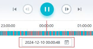

Recording Download
Configuring Recording Download
Personal Settings
- Choose Maintenance Management > Personal Settings on the iClient S100 home page.
- Set recording download parameters. Table 3-82 describes the parameters.Table 3-82 Parameter description
Parameter
Description
Default Clip Length (5 min - 48 hours)
Default duration of a video clip that is manually recorded. This parameter applies to both manual local recording and manual server recording.
Split Files Every
Mode for splitting a recording file into multiple smaller data files.
This parameter applies to manual local recording and recording download without encryption.
The options are as follows:
- Time (min): by time
- Capacity (MB): by storage space
Reserved Space (MB)
Minimum disk space for storing recordings. To ensure that recordings can be stored properly, the available disk space must be greater than the minimum disk space.
Space Limit Warning (MB)
Disk storage threshold for triggering an alarm. During video recording, when the available disk space is less than the value of this parameter, the system generates an alarm. In addition, the value of this parameter must be greater than that of Reserved Space (MB).
Format
Video file storage format. The default value is MP4.
Naming Format
Rule for naming a recording file.
This parameter applies to manual local recording and recording download.
The options are as follows:
- Camera name_No._Time (YYYY-MM-DD-hh-mm-ss)
- Camera name_Time (YYYY-MM-DD-hh-mm-ss)_No.
- Time (YYYY-MM-DD-hh-mm-ss)_Camera name_No.
Download Threads
Maximum number of recordings that can be downloaded at the same time.
Download Speed (from Server)
Download speed. Server recordings can be downloaded at 1/4, 1/2, or 1x camera bit rate, or high speed (maximum speed that the server, client, and current network can bear). If the bit rate is 4 Mbit/s, 1/4 of it is 1 Mbit/s.
Skip Losses Under (s)
Maximum time interval for ignored interruption. During recording search, if the recording is interrupted for a specified period that is less than the value of this parameter, the recording is played as a complete one without any interruption.
- Click Save.
Local Settings
- Choose Maintenance Management > Local Settings on the iClient S100 home page.
- Set Download Server-based Recordings to under Recording Directories, and click Save.
Configuring Recording Download
You can download recordings from the server and cameras to your local computer for later viewing. This function is sensitive. Therefore, you are advised to implement control on recording download, for example, control the content, quantity, size, and download time of recordings.
On the iClient S100, you can download recordings in either of the following ways:
- Search for recordings on the Playback page and download the recordings. For details, see Downloading Recordings on the Recording Playback Page.
- Choose Basic Operations > Media > Recordings, search for recordings by criteria, and download the recordings. For details, see Downloading Recordings on the Networked Video Page.
- All export and import functions can be used only in the environments that meet the following requirements:
- The WPS Office software is used by default.
- Microsoft Office (later than 2007) has been installed properly and its valid license has been activated. The software is running properly.
- You are advised to use a professional video or image editing tool to shield irrelevant persons in downloaded or exported video or images and meet the HD requirements of the data subject. The recommended procedure is as follows:
- Download the required video to the local computer and decompress it to common video or export image data to the local computer.
- Use a video or an image editing tool to anonymize irrelevant targets and only retain the HD part of the data subject.
- Export the anonymized video or images to meet the data transfer requirements of the data subject.
- To ensure personal information security, delete the downloaded or exported images and recordings in a timely manner.
- All export and import functions can be used only in the environments that meet the following requirements:
Downloading Recordings on the Recording Playback Page
- Choose Basic Operations > Playback on the iClient S100 home page.
- Select a camera whose recordings are to be downloaded in Devices.
- In the recording search area, set search criteria and click Search.
- In the search result, click
 on the right of a timeline and click Download to switch to the recording download mode.
 - Drag the slider on the timeline to select time segments for recording download, as shown in Figure 3-114.
- Download the recordings to a local directory.
- Single download
- Click
 .
. - Set Video and click OK to download the recording generated in the selected time segment to the specified local directory.
- Click
- Batch download
Click
 to download recordings of multiple time segments of the current camera to the specified local directory. You can also download encrypted recordings of multiple time segments to the specified local directory.
- Single download
- Choose Basic Operations > Media > Downloads > All on the iClient S100 home page to view the recording download progress.
After the download is complete, go to the local directory to view the downloaded recordings.
- If the recordings are in H.265 encoding format, you are advised to use the VLC player for playback.
- If the network condition is poor, the camera bit rate is high, and UDP is used for data transmission between the local domain and the external domain, packets may be lost when you download recordings from an external domain at a high speed.
- Recordings in MJPEG encoding format cannot be downloaded.
- If the built-in player fails to play back the downloaded recordings, you are advised to download the VLC player or other common players for playback.
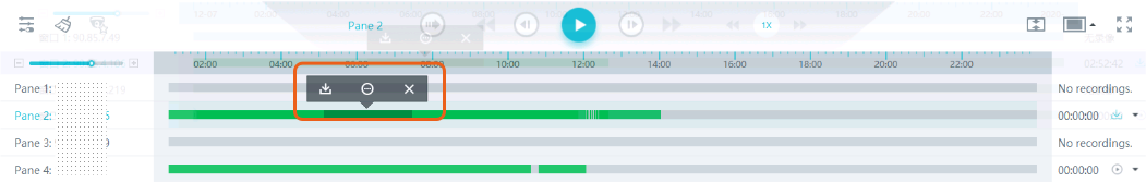
Downloading Recordings on the Networked Video Page
- Choose Basic Operations > Media > Recordings on the iClient S100 home page.
- Set search criteria and click Search. Table 3-83 describes the search parameters.Table 3-83 Parameter description
Parameter
Description
Camera
Source cameras of recordings to be searched. You can select cameras from the device list or on the map.
Period
Period during which recordings to be searched are generated.
The search result varies according to the recording type.
- When Recording Type is set to Scheduled or Normal alarm triggered, recordings whose time spans intersect with the value of Period are displayed in search results.
- When Recording Type is set to Bookmarked, recording bookmarks attached during the specified recording time in Period are displayed in search results.
Recording Type
Type of recordings to be searched.
- Download recordings to a local directory.
- On the timeline of the camera whose recordings need to be downloaded, select the recording segment to be downloaded and click
 .
. - Set Video and Save Path.
- Click OK to download the recordings generated in the selected time segments to the specified local directory.
- (Optional) Download recordings in batches. Select source cameras, select recording segments, and click
 in the upper right corner to download the selected recording segments to the local computer.
 If you do not select recording segments, all recordings from the current camera are downloaded by default.
- On the timeline of the camera whose recordings need to be downloaded, select the recording segment to be downloaded and click
Local Settings
This section describes how to set local parameters on the iClient S100 and save the settings to local computers. For example, user A and user B can both use account C to modify local settings and save the settings to their own local computers, respectively. The local settings of user A and user B do not affect each other. You can set parameters in the following areas on the Local Settings page:
- Recording Directories
- Snapshot Directories
- Others
Parameter/Button |
Description |
|
|---|---|---|
Recording Directories |
Save Local Recordings to |
Local path for storing recordings generated on the iClient S100. |
Download Server-based Recordings to |
Local path for storing downloaded recordings. |
|
Snapshot Directories |
Save Local Snapshots to |
Local path for storing snapshots taken on the iClient S100. |
Others |
Enable IVS Debug Log |
Indicates whether to enable the IVS debug log function for viewing IVS debug logs. This function is enabled by default. |
Enable Local Debug Log |
Indicates whether to enable the local debug log function for viewing debug logs on the local computer. To enable the function, set this parameter to Yes. You can click Open Log Directory to go to the directory for storing client logs on the local computer. |
|
GPU Acceleration |
Indicates whether to enable GPU acceleration. To use GPU decoding, set this parameter to Yes. |
|
Decode Only I-Frames for Live Video If CPU Usage Exceeds 90% |
Indicates whether to enable the function of decoding only I-frames for live video viewing to reduce the CPU and memory usage. |
|
Decode Only I-Frames for Playback If CPU Usage Exceeds 90% |
Indicates whether to enable the function to reduce the CPU and memory usage. |
|
Decoding Format |
The decoding format can be HME or FFmpeg. |
|
Auto-Lock Screen |
Indicates whether to automatically lock the screen when no operation is performed within the configured interval. This function is enabled by default. |
|
Target Intelligence Enabled |
You can enable and use functions related to target recognition on the iClient S100 only after you set this parameter to Yes and read and agree to the Intelligent Vision Target Recognition Service Agreement. |
|
Diagnosis |
Client Log Export |
Button for exporting iClient S100 logs, CUServer logs, and ZKBioSecurity service logs with one click. |